Article
Low-Impact Muscle Simulator
with treatment programs
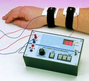
This is a DIY version of a device that can be found in various forms in the clinics of physiotherapists and massage institutes. It produces a series of electrical shocks that stimulate the muscles. The intensity and duration of the shocks are adjustable, and we have given great attention to the safety of this device.Anyone who has ever visited the clinic of a physiotherapist or a sports masseur will have been amazed at the large amount of complex-looking equipment to be found there. In this area, as in many others, modern technology (and in particular electronics technology) has become indispensable in a relatively short time.One type of equipment that is most often used by these people is a muscle stimulator. There are all sorts of different models available with a variety of names, but they all work in essentially the same manner. Two electrodes are attached to some part of the body a small ways apart, and a pulsating current is passed between the electrodes. The objective of this is to stimulate the muscle located between the electrodes.
Materials
Gerber file
CAM/CAD data for the PCB referred to in this article is available as a Gerber file. Elektor GREEN and GOLD members can exclusively download these files for free as part of their membership. Gerber files allow a PCB to be produced on an appropriate device available locally, or through an online PCB manufacturing service.
Elektor recommends the Elektor PCB Service service from its business partner Eurocircuits or AISLER as the best services for its own prototypes and volume production.
The use of our Gerber files is provided under a modified Creative Commons license. Creative Commons offers authors, scientists, educators and other creatives the freedom to handle their copyright in a more free way without losing their ownership.
PCB
Component list
Resistors:
R1,R4-R12,R15,R16 = 1k?
R2,R3,R14 = 4k?7
R13 = 22k?
R17 = 10k?
P1 = 50k? linear potentiometer
Capacitors:
C1 = 100nF
C2 = 10µF 63 V radial
C3,C4 = 33pF
C5 = 47µF 25V radial
C6,C7 = 100µF 16V radial
Semiconductors:
D1-D4 = high-efficiency-LED, red (3 mm)
D5 = 1N4001
D6 = 1N4148
D7,D8 = zener diode 39V/0.4W
T1,T2 = BUZ11 (BUZ10, BUZ100)
T3 = BD140
IC1 = 89C2051-12PC (programmed), order code 000041-41
IC2 = 7805 (or LM2940T-5, 4805)
Miscellaneous:
S1-S4 = Digitast pushbutton (ITT/Schadow)
S5 = on/off switch
Tr1 = 100-V line output transformer 0-4-16 ?/20 W (Conrad Electronics or Monacor/Monarch)
X1 = 12 MHz quartz crystal
LD1,LD2 = HD1131O
Enclosure: e.g., TEKO 160x95x61 mm
PC1-PC4 = miniature wander sockets
Disk, project software (source code and hex code): order code 000041-11
Discussion (0 comments)