Article
Voice shifter
original effects unit

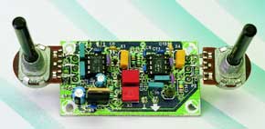
Effects units are and remain popular, especially with pop musicians. These units, phasers, clippers, flangers, and so on are used to make a specific sound or range of sounds. This article describes how such an effects unit may be built from simple means. It is another application of the pitch shifting technique as used in phasing, chorus and flanging, but, unlike true pitch shifting in which a constant interval is created above or below the input signal, it shifts a specific audio band.It has been said before, and will no doubt be said again many times: we live in a funny world. Most music lovers go out of their way and are prepared to spend a lot of money to achieve music reproduction with as little distortion as possible.There are, however, others (lovers of a different type of music) who go to great lengths to get away from high fidelity sound. These people feel that the sound processing must match their ideas of what music should be.
Materials
Gerber file
CAM/CAD data for the PCB referred to in this article is available as a Gerber file. Elektor GREEN and GOLD members can exclusively download these files for free as part of their membership. Gerber files allow a PCB to be produced on an appropriate device available locally, or through an online PCB manufacturing service.
Elektor recommends the Elektor PCB Service service from its business partner Eurocircuits or AISLER as the best services for its own prototypes and volume production.
The use of our Gerber files is provided under a modified Creative Commons license. Creative Commons offers authors, scientists, educators and other creatives the freedom to handle their copyright in a more free way without losing their ownership.
PCB
Component list
Resistors:
R1 = 150k?
R2 = 680?
R3 = 1k?5
R4 = 10k?
R5 = 220k?
R6 = 100k?
P1,P2 = 100k? linear potentiometer
Capacitors:
C1,C2,C16 = 100nF MKT (Siemens)
C3,C9,C10,C11,C17,C19 = 100nF ceramic
C4 = 270pF
C5 = 33pF
C6,C13 = 1nF ceramic
C7,C8 = 39pF
C12,C14 = 150pF
C15 = 15nF MKT (Siemens)
C18 = 10µF 63V radial
C20 = 100µF 16V radial
Semiconductors:
D1 = BB509 (ITT)*
D2 = 1N4002
IC1,IC2 = NE612N/SA612AN (Philips)*
IC3 = 7806
Miscellaneous:
X1,X4 = CSB455 (Murata)*
X2,X3 = SFD455A (Murata)*


Discussion (0 comments)