

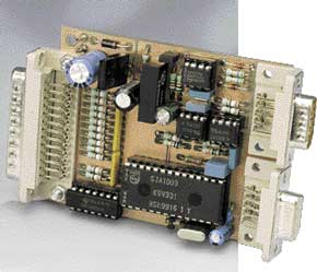
PC Interface for the CAN Bus
with new software
This is a MEMBER ONLY article. You need a subscription to read this article.
- Access to Elektor archive and 5,000+ Gerber files
- Receive up to 8 magazines per year (digital and/or paper)
- 10% discount in the Elektor store
Available from €4.95 per month.
What is Members Only
Elektor is committed to providing high-quality content on electronics, catering to tens of thousands of paying members. As part of this commitment, Elektor has launched Premium, an initiative that offers exclusive online articles to members sometimes even before they appear in the magazine.
Every day, members can access in-depth articles that showcase the best of Elektor's premium content.
This initiative aims to reward members with early access. Once logged in, members can easily enjoy this exclusive content and engage in discussions about featured projects. While Premium adds to the existing resources available, Elektor will continue to provide a wealth of free information.
Join the Elektor community today to take advantage of Premium and other benefits!
Materials
Gerber file
CAM/CAD data for the PCB referred to in this article is available as a Gerber file. Elektor GREEN and GOLD members can exclusively download these files for free as part of their membership. Gerber files allow a PCB to be produced on an appropriate device available locally, or through an online PCB manufacturing service.
Elektor recommends the Elektor PCB Service service from its business partner Eurocircuits or AISLER as the best services for its own prototypes and volume production.
The use of our Gerber files is provided under a modified Creative Commons license. Creative Commons offers authors, scientists, educators and other creatives the freedom to handle their copyright in a more free way without losing their ownership.
Component list
R1-R12,R17,R18,R19,R21 = 390?
R13 = 4k?7
R14,R15,R20 = 10k?
R16 = 56k?
R22,R23 = 5?6
R24 = 120?
R25 = 4-way SIL arary 4k?7
R26 = 8-way-SIL array 4k?7
Capacitors:
C1,C2 = 22pF
C3 = 10µF 25V radial
C4,C9,C10,C11 = 100nF, 5 mm raster
C5 = 470µF 25V radial
C6 = 220µ 10V radial
C7 = 100µ 10V radial
C8 = 1µF 10V or solid MKT raster 5mm
Semiconductors:
D1,D2 = zener diode 12V 400 mW
D3 = 1N4004
IC1 = PCA82C200 or SJA1000 * (Philips)
IC2,IC3 = 6N137 (Toshiba)
IC4 = PCA82C250 (Philips)
IC5 = NMV0505SA (Newport, Farnell #589 810)
IC6 = 7805
Miscelllaneous:
JP1 = Jumper
K1 = 9-way sub-D plug (male), PCB mount.
K2 = 9-way sub-D socket (female), PCB mount.
K3 = 25-waySub-D plug (male), PCB mount
2 solder pins
X1 = 16 MHz quarz crystal
Disk, order code 006004-1 (DOSInterface and source code in C)
PCB, order code 000039-1
Discussion (0 comments)