Article
Transmitter for Fibre-Optic IR Extender

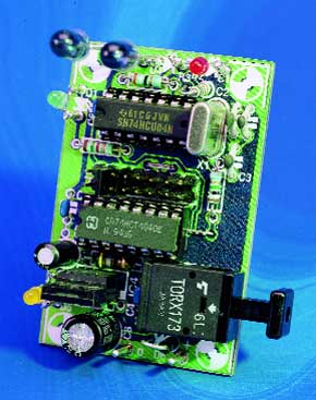
This circuit restores the original modulation of the signal received from the remote-control unit, which was demodulated by the receiver unit at the other end of the extender (see ‘Receiver for fibre-optic IR extender’).If no signal is received, the Toslink transmitter in the receiver is active, so a High level is present at the output of the Toslink receiver in this circuit. Buffer IC2a then indicates via LED D1 that the receiver unit is active.
Materials
Gerber file
CAM/CAD data for the PCB referred to in this article is available as a Gerber file. Elektor GREEN and GOLD members can exclusively download these files for free as part of their membership. Gerber files allow a PCB to be produced on an appropriate device available locally, or through an online PCB manufacturing service.
Elektor recommends the Elektor PCB Service service from its business partner Eurocircuits or AISLER as the best services for its own prototypes and volume production.
The use of our Gerber files is provided under a modified Creative Commons license. Creative Commons offers authors, scientists, educators and other creatives the freedom to handle their copyright in a more free way without losing their ownership.
PCB
Component list
Resistors:
R1 = 1M?
R2 = 1k?5
R3,R5 = 1k?
R4 = 39 ?
Capacitors:
C1,C2 = 33pF
C3 = 15pF
C4,C5,C6 = 100nF ceramic
C7 = 4µF7 63V radial
C8 = 220µF 25V radial
Inductors:
L1 = 47µH
Semiconductors:
D1 = high-efficiency LED, green
D2 = high-efficiency LED, red
D3,D4 = LD271
D5 = high-efficiency LED, yellow
D6 = 1N4002
IC1 = TORX173 (Toshiba)
IC2 = 74HCU04
IC3 = 74HCT4040
IC4 = 7805
Miscellaneous:
J1 = 16-way double contact row, plus jumper
X1 = 18.432MHz quartz crystal


Discussion (0 comments)