Article
Valve Preamplifier (2)
Construction, first part
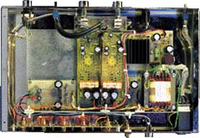
You should use only the best components to build a high-end amplifier, if you want to achieve and maintain the specified performance figures.It is also important that you observe the suggestions given in the text and the components lists, and avoid using inferior-quality ‘equivalent’ types. All printed circuit boards supplied by Experience Electronics for this project are made using fibreglass-reinforced epoxy with a 70-µm copper lamination. All resistors in the components list are 1-percent tolerance, 0.7-W metal film types, unless otherwise indicated, with a lead spacing of 10 mm. The 2-W and 4.5-W resistors are metal oxide types with a tolerance of 5 percent, and have lead spacings of 15 mm and 25 mm respectively. The gold-plated Cinch sockets, as well as the potentiometers, should of course be very high quality.
Component list
Input Board
Resistors:
R1-R8 = 100k
Rx = see text
Re1-Re8 = SIL reed relay, 12V, 1 make contact
Miscellaneous:
K1-K9 = cinch sockets, chassis mount
Two cinch sockets, chassis mount, for recorder outputs
S1 = rotary switch, 1 pole, 4 contacts, break before make
Solder pins
Copper foil
Amplifier Board (one channel)
Resistors:
R1 = 680k
R2 = 1k 8
R3 = 10k
R4 = 33k
R5 = 2k 2
R6 = 150k , 2W
R7 = 470k , 2W
R8 = 2k 7
R9 = 8k 2
R10 = 680k
R11 = 150
R12 = 270
R13 = 27k
R14 = 150 , 2W
R15,R16 = 6k 8, 4.5W
Capacitors:
C1 = 1µF 63V, 5mm raster
C2 = 10µF 400V, 5mm raster
C3 = 47µF 40V, 5mm raster
C4 = 2µF2 400V, 5mm raster
C5 = 220µF 40V, 5mm raster
C6 = 47µF 450V, size 18.5x41mm
C7,C8 = 22µF 400V, 7.5mm raster
C9 = see text
Miscellaneous:
D1 = see text
V1 (Rö1) = ECL86
1 ceramic ‘Noval’ (9-pin) socket, PCB mount
Copper foil
Solder pins
Protection Circuit
Resistors:
R1,R2 = 10k
R3 = 33k
R4 = 1k
R5,6 = 33k
R7 = 100k
R8 = 10
R9 = 10k
R10 = 390k
R11 = 100k
R12 = 10k
R13 = 100k
Capacitors:
C1 = 0.22µF MKT, raster 7.5mm
C2 = 0.33µF MKT, raster 7.5mm
C3 = 10nF ceramic, raster 5mm
C4,C5 = 1µF 63V, raster 5mm
C6 = 220µF 40V, raster 5mm
C7 = 47µF 40V, raster 5mm
Semiconductors:
D1,D3 = 1N4007
D2,D6 = zener diode 12 V, 1.3W
D4,D7 = 1N4148
D5 = BAT43
T1 = BC546B
T2 = BD139-16
IC1 = 555
IC2 = 4023
Miscellaneous:
1 off 8-way DIL IC socket, gold-plated contacts
1 off 14-way DIL IC socket, gold-plated contacts
Solder pins
Resistors:
R1-R8 = 100k
Rx = see text
Re1-Re8 = SIL reed relay, 12V, 1 make contact
Miscellaneous:
K1-K9 = cinch sockets, chassis mount
Two cinch sockets, chassis mount, for recorder outputs
S1 = rotary switch, 1 pole, 4 contacts, break before make
Solder pins
Copper foil
Amplifier Board (one channel)
Resistors:
R1 = 680k
R2 = 1k 8
R3 = 10k
R4 = 33k
R5 = 2k 2
R6 = 150k , 2W
R7 = 470k , 2W
R8 = 2k 7
R9 = 8k 2
R10 = 680k
R11 = 150
R12 = 270
R13 = 27k
R14 = 150 , 2W
R15,R16 = 6k 8, 4.5W
Capacitors:
C1 = 1µF 63V, 5mm raster
C2 = 10µF 400V, 5mm raster
C3 = 47µF 40V, 5mm raster
C4 = 2µF2 400V, 5mm raster
C5 = 220µF 40V, 5mm raster
C6 = 47µF 450V, size 18.5x41mm
C7,C8 = 22µF 400V, 7.5mm raster
C9 = see text
Miscellaneous:
D1 = see text
V1 (Rö1) = ECL86
1 ceramic ‘Noval’ (9-pin) socket, PCB mount
Copper foil
Solder pins
Protection Circuit
Resistors:
R1,R2 = 10k
R3 = 33k
R4 = 1k
R5,6 = 33k
R7 = 100k
R8 = 10
R9 = 10k
R10 = 390k
R11 = 100k
R12 = 10k
R13 = 100k
Capacitors:
C1 = 0.22µF MKT, raster 7.5mm
C2 = 0.33µF MKT, raster 7.5mm
C3 = 10nF ceramic, raster 5mm
C4,C5 = 1µF 63V, raster 5mm
C6 = 220µF 40V, raster 5mm
C7 = 47µF 40V, raster 5mm
Semiconductors:
D1,D3 = 1N4007
D2,D6 = zener diode 12 V, 1.3W
D4,D7 = 1N4148
D5 = BAT43
T1 = BC546B
T2 = BD139-16
IC1 = 555
IC2 = 4023
Miscellaneous:
1 off 8-way DIL IC socket, gold-plated contacts
1 off 14-way DIL IC socket, gold-plated contacts
Solder pins
Discussion (0 comments)