Article
Valve Preamplifier (2a)
Construction (continued) and test data

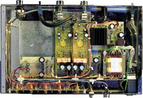
Once you’ve stuffed all the boards that go into the design, the Valve Preamplifier is ready for assembling and wiring. The results (see pictures and performance data) are pretty convincing.Next comes the volume control board (see Figure 2). The photograph shows how it is built. There is nothing difficult about mounting the components, and the board can be solidly attached to the front panel via the potentiometers, using suitable hardware.The output relays and the headphone socket are mounted on the small circuit board shown in Figure 5. The socket is also used to fix the board to the chassis, so no additional fitting hardware is needed. You must pay careful attention to where the signal from the amplifier comes from and where is it goes to afterwards. The headphone socket is protected only if the wiring is done properly.
Component list
Volume Control
Resistors:
R1,R1´= 100?
R2,R2´,R4,R4´= 3k?9
R3,R3´= 470?
R5,R5´= 10k?
P1 = 10k? stereo potentiometer, linear, tracking
P2 = 10k? stereo potentiometer, linear, tracking
2 holders for potentiometers
Miscellaneous:
S1 = rocker switch, 2 poles, 3 contacts
Solder pins
High Voltage Supply
Resistors:
R1 = 10k?, 2W
R2 = 100?, 4.5W
R3,R4 = 1k?
R5 = 6?8, 2W
R6 = 150k?, 2W
Capacitors:
C1 = 100µF 400V, raster 10mm
C2,C3 = 22µF 400V, raster 7.5mm
Semiconductors:
T1 = BUZ92
T2 = BC546
D1,D2,D3 = zener diode 110V, 1.3W
D4 = zener diode 18V, 1.3W
Gl1 = B500C1500, rectangular case (500V piv, 1.5A peak)
Miscellaneous:
Heatsink for T1: SK 68/50 (Fischer, Dau Components)
Isolation and mounting material for T1 and heatsink
Solder pins
Headphones/Line Switch
K1 = stereo headphones socket, PCB mount
Re1,Re2 = relay, 1 changeover contact, 12V coil (Omron G6E)
R1,R2 = 680k?
Low Voltage Supply
Capacitors:
C1 = 2200µF 40V, raster 7.5mm
C2 = 100µF 40V, raster 5mm
C3,C4 = 100nF, ceramic, raster 5mm
Semiconductors:
Gl1 = B80C1500, rectangular case (80V piv, 1.5A peak)
D1 = 1N4148
IC1 = 7812
Miscellaneous:
Isolation material for IC1
Si1,Si2 = fuse, 0.2 A, slow, with PCB mount holder
Solder pins
Resistors:
R1,R1´= 100?
R2,R2´,R4,R4´= 3k?9
R3,R3´= 470?
R5,R5´= 10k?
P1 = 10k? stereo potentiometer, linear, tracking
P2 = 10k? stereo potentiometer, linear, tracking
2 holders for potentiometers
Miscellaneous:
S1 = rocker switch, 2 poles, 3 contacts
Solder pins
High Voltage Supply
Resistors:
R1 = 10k?, 2W
R2 = 100?, 4.5W
R3,R4 = 1k?
R5 = 6?8, 2W
R6 = 150k?, 2W
Capacitors:
C1 = 100µF 400V, raster 10mm
C2,C3 = 22µF 400V, raster 7.5mm
Semiconductors:
T1 = BUZ92
T2 = BC546
D1,D2,D3 = zener diode 110V, 1.3W
D4 = zener diode 18V, 1.3W
Gl1 = B500C1500, rectangular case (500V piv, 1.5A peak)
Miscellaneous:
Heatsink for T1: SK 68/50 (Fischer, Dau Components)
Isolation and mounting material for T1 and heatsink
Solder pins
Headphones/Line Switch
K1 = stereo headphones socket, PCB mount
Re1,Re2 = relay, 1 changeover contact, 12V coil (Omron G6E)
R1,R2 = 680k?
Low Voltage Supply
Capacitors:
C1 = 2200µF 40V, raster 7.5mm
C2 = 100µF 40V, raster 5mm
C3,C4 = 100nF, ceramic, raster 5mm
Semiconductors:
Gl1 = B80C1500, rectangular case (80V piv, 1.5A peak)
D1 = 1N4148
IC1 = 7812
Miscellaneous:
Isolation material for IC1
Si1,Si2 = fuse, 0.2 A, slow, with PCB mount holder
Solder pins


Discussion (0 comments)