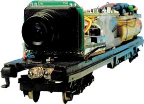
Camera on Model Train
view the track from the proper perspective

This is a MEMBER ONLY article. You need a subscription to read this article.
- Unlimited access to online Member Only articles
- 3 new editions Elektor Magazine (digital)
- More than 5000 Gerber files
- 20% member discount on e-books (at elektor.com)
- 10% member discount on Products (at elektor.com)
Available from €5.33 per month.
What is Members Only
Elektor is committed to providing high-quality content on electronics, catering to tens of thousands of paying members. As part of this commitment, Elektor has launched Premium, an initiative that offers exclusive online articles to members sometimes even before they appear in the magazine.
Every day, members can access in-depth articles that showcase the best of Elektor's premium content.
This initiative aims to reward members with early access. Once logged in, members can easily enjoy this exclusive content and engage in discussions about featured projects. While Premium adds to the existing resources available, Elektor will continue to provide a wealth of free information.
Join the Elektor community today to take advantage of Premium and other benefits!
Materials
Gerber file
CAM/CAD data for the PCB referred to in this article is available as a Gerber file. Elektor GREEN and GOLD members can exclusively download these files for free as part of their membership. Gerber files allow a PCB to be produced on an appropriate device available locally, or through an online PCB manufacturing service.
Elektor recommends the Elektor PCB Service service from its business partner Eurocircuits or AISLER as the best services for its own prototypes and volume production.
The use of our Gerber files is provided under a modified Creative Commons license. Creative Commons offers authors, scientists, educators and other creatives the freedom to handle their copyright in a more free way without losing their ownership.
Component list
R1 = 270?
R2,R4 = 470? (option 1)
R3 = 270k?
R5,R8,R12 = 33? (option 1)
R7,R9,R10,R11 = 33?
R6 = 10k?
Capacitors:
C1,C2 = 22pF ceramic
C3 = 220µF 25 V radial
C4 = 47µF 25V radial
C5 = 470µF 16V radial
C6 = 47µF 16V radial
C7,C9 = 100nF
C8 = 47µF 6V radial
Inductors:
L1 = 33 µH (40 turns. 0.25 mm diam./SWG32 enamelled copper wire on ferrite rod, 4 mm dia., 15 mm long)
L2 = 150 µH miniature choke
Semiconductors:
D1,D3,D10 = 1N4001
D2,D5-D8 = SB130
D4,D9 = 1N4148 (option 1)
D11,D12 = high-power IR-LED (option 1)
T1 = not fitted
T2 = BC847 of BC547 (option 1)
IC1 = LT1301CN8 (Linear Technology)
IC2 = LM2940CT
IC3 = 78L05 (only with 5V camera)
IC4 = PIC16F84 (programmed, for Super-Loco Decoder, # 996523-1
IC5 = ULN2004
Miscellaneous:
X1 = 4 MHz quartz crystal
L1,L2 = miniature bulb 5V/50mA (option 2)
PCB, order code 000129-1


Discussion (0 comments)