Article
Emulator for 27C256 EPROM
with RS232 control
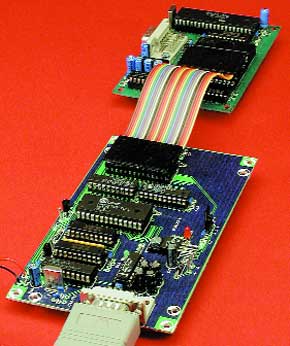
Going through our archives we discovered that it’s been almost ten years since we published an EPROM emulator. The version we propose in this article should meet today’s demands of hobbyists wishing to debug microcontroller systems based on an EPROM. We have chosen the 27C256 because it is cheap and currently the most widely used EPROM in the hobby area.An EPROM emulator is a development tool designed to facilitate code debugging and code writing jobs on circuits incorporating an EPROM (electrically erasable read only memory). An EPROM, as most of you will know, can not be reprogrammed before its previous contents has been erased through exposure to a certain amount of ultraviolet (UV) light. So, even for the smallest modification to the code in your EPROM, you need to do a complete eraseandreprogram cycle, which is tedious and costly given the time lost and the price of an UV eraser box.
Materials
Gerber file
CAM/CAD data for the PCB referred to in this article is available as a Gerber file. Elektor GREEN and GOLD members can exclusively download these files for free as part of their membership. Gerber files allow a PCB to be produced on an appropriate device available locally, or through an online PCB manufacturing service.
Elektor recommends the Elektor PCB Service service from its business partner Eurocircuits or AISLER as the best services for its own prototypes and volume production.
The use of our Gerber files is provided under a modified Creative Commons license. Creative Commons offers authors, scientists, educators and other creatives the freedom to handle their copyright in a more free way without losing their ownership.
PCB
Component list
Resistors:
R1,R2 = 1.5 k-ohm
R3,R7 = 12 k-ohm
R4 = 10 k-ohm
R5,R6 = 4.7 k-ohm
R8 = 10 k-ohm 8-way SIL array
Capacitors:
C1,C2,C16,C17 = 10µ F 35V
C3 =47µ F 35V
C4-C9,C13-C15 =100nF
C10 =1µ F 16V
C11,C12 =33pF
Semiconductors:
D1 = 1N4001
D2,D3 = high efficiency LED
T1,T2 = BS170
IC1 = MAX232 (Maxim)
IC2 = AT89C2051 (Atmel), programmed, order code 000153-41
IC3,IC4 = 74HCT573
IC5 = 62256 (RAM)
IC6,IC7,IC8 = 74HCT541
IC9 = EPROM being emulated
IC10 = 7805
Miscellaneous:
K1=9-way sub-D socket (female), PCB mount
PC1-PC4= solder pin
JP1= 3-way SIL pinheader with jumper
S1= pushbutton, 1 make contact
X1=12MHz quartz crystal
PCB, order code 000153-1
Disk, project software, order code 000153-11
Discussion (0 comments)