Article
MIDI to Voltage Converter
with 16 independent voltage sources
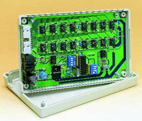
Although MIDI (Musical Instrument Digital Interface) was originally developed for controlling musical instruments, it can also be used for numerous other purposes. In the circuit presented here, MIDI signals are used to set a number of DC voltages. Up to 16 output voltages can be independently adjusted.Nowadays, every computer has a sound card, and the sound card always has a MIDI interface. However, in most cases the MIDI interface is not used. Most people control their musical instruments using MIDI commands (if they actually have any musical instruments…).A microprocessor forms an excellent starting point for building a circuit that responds to MIDI commands. In this case, the author has developed a circuit that allows the values of several DC voltages to be set in a simple manner. These could be used for measurement applications, for example. From 1 to 16 channels are possible, with each channel having its own D/A converter and an adjustable output voltage ranging from 0 to 5 V.
Materials
Gerber file
CAM/CAD data for the PCB referred to in this article is available as a Gerber file. Elektor GREEN and GOLD members can exclusively download these files for free as part of their membership. Gerber files allow a PCB to be produced on an appropriate device available locally, or through an online PCB manufacturing service.
Elektor recommends the Elektor PCB Service service from its business partner Eurocircuits or AISLER as the best services for its own prototypes and volume production.
The use of our Gerber files is provided under a modified Creative Commons license. Creative Commons offers authors, scientists, educators and other creatives the freedom to handle their copyright in a more free way without losing their ownership.
PCB
Component list
Resistors:
R1,R3 = SIL array 4 x 10 k-ohm
R2 = 33 k-ohm
R4 = 470 ohm
R5 = 220 ohm
R6,R7 = 10 k-ohm
Capacitors:
C1 = 4µ F7 16V radial
C2,C3 = 27pF
C4,C7-C10 = 100nF
C5 = 470µ F 25V radial
C6 = 10µ F 16V radial
Semiconductors:
D1 = 1N4148
D2 = 1N4001
IC1 = programmed PIC16F84-10/p, order code 000158-41
IC2 = 6N138
IC3 = 7805
IC4 = TL061
IC5-IC20 = LTC1452CN8
Miscellaneous:
K1 = 5-way DIN socket, PCB mount, receptacles at 180°
K2 = 20-way boxheader, angled pins
K3 = mains adapter socket, PCB mount
S1,S2 = 4-way DIP switch
X1 = 10MHz quartz crystal
Disk, contains source code and hex code files, order code 000158-11
Discussion (0 comments)