

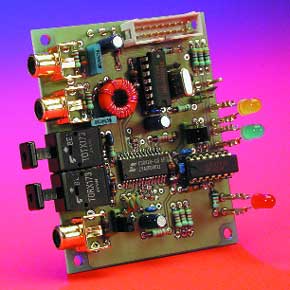
96 kHz Sampling Rate Converter
for high-end digital audio
This is a MEMBER ONLY article. You need a subscription to read this article.
- Unlimited access to online Member Only articles
- 3 new editions Elektor Magazine (digital)
- More than 5000 Gerber files
- 20% member discount on e-books (at elektor.com)
- 10% member discount on Products (at elektor.com)
Available from €5.33 per month.
What is Members Only
Elektor is committed to providing high-quality content on electronics, catering to tens of thousands of paying members. As part of this commitment, Elektor has launched Premium, an initiative that offers exclusive online articles to members sometimes even before they appear in the magazine.
Every day, members can access in-depth articles that showcase the best of Elektor's premium content.
This initiative aims to reward members with early access. Once logged in, members can easily enjoy this exclusive content and engage in discussions about featured projects. While Premium adds to the existing resources available, Elektor will continue to provide a wealth of free information.
Join the Elektor community today to take advantage of Premium and other benefits!
Materials
Gerber file
CAM/CAD data for the PCB referred to in this article is available as a Gerber file. Elektor GREEN and GOLD members can exclusively download these files for free as part of their membership. Gerber files allow a PCB to be produced on an appropriate device available locally, or through an online PCB manufacturing service.
Elektor recommends the Elektor PCB Service service from its business partner Eurocircuits or AISLER as the best services for its own prototypes and volume production.
The use of our Gerber files is provided under a modified Creative Commons license. Creative Commons offers authors, scientists, educators and other creatives the freedom to handle their copyright in a more free way without losing their ownership.
Component list
R1,R16,R18 = 75Ohm
R2 = 5kOhm 1, SMD (Farnell # 771-429, case size 0805)
R3 = see text
R4-R7 = 47kOhm
R8 = 2Ohm 2
R9-R12 = 47Ohm
R13 = 4Ohm 7
R14 = 8kOhm 2
R15,R17 = 270Ohm
R19 = 100kOhm
R20 = 1MOhm
R21,R22,R23 = 1kOhm
R24 = 3kOhm 9
R25 = 1Ohm 5
Capacitors:
C1,C2 = 10nF ceramic
C3 = 82nF, SMD, (Farnell # 301-9550, dielectric X7R, case size 0603)
C4 = 2nF2, SMD (Farnell # 578-290, dielectric NPO, case size 0805)
C5,C8 = 1nF, SMD (Farnell # 301-9380, dielectric X7R, case size 0402)
C6,C9 = 100nF, SMD (Farnell # 432-210, dielectric X7R, case size 0603)
C7,C10 = 1µF, SMD (Farnell # 317-627, dielectric NP0, case size 0805)
C11,C13,C15,C16,C19,C25,C26,C28 = 100nF ceramic
C12,C14,C24 = 100µF 10V radial
C17,C18 = 47nF, MKT (Siemens, Electrovalue)
C20,C21 = 33pF
C22 = 27pF
C23 = 100pF
C27 = 10µF 63V radial
C29 = 1000µF 25V radial
C30-C33 = 22nF, ceramic
Inductors:
L1,L3 = 10 µH
L2 = 47µH
L4 = 1.5µ H or 1.8 µH (see text)
Semiconductors:
B1 = B80C1500 (rectangular case, 80V piv, 1.5A peak)
D1,D5 = high-efficiency LED, red
D2 = high-efficiency LED, yellow/amber
D3 = high-efficiency LED, green
D4 = zener diode 5.6V, 1.3W
IC1 = CS8420-CS (Crystal, 28-pin SOIC; Atlantik Elektronik, Germany)
IC2 = TORX173 Toshiba (Conrad Electronics)
IC3 = TOTX173 Toshiba (Conrad Electronics)
IC4 = 74HCU04
IC5 = 74HC14
IC6 = 7805
Miscellaneous:
JP1,JP2 = 3-way pinheader + jumper
JP3 = 2-way pinheader + jumper
K1,K2,K3 = RCS (line) socket, PCB mount, (e.g. Monacor/Monarch type T-709G)
K4 = 16-way straight boxheader
K5,K6 = 2-way PCB terminal block, lead pitch 7.5 mm
X1 = 24.576 MHz quartz crystal (Cload = 20 pF, parallel resonance)
F1 = fuse, 32 mAT (time lag) +PCB mount fuse holder
Tr1 = ferrite core, Philips type TN/7,5/5-3E25, primary 20 turns, secondary 2x2 turns ECW 0.5 mm dia. ( 26 SWG)
Tr2 = mains transformer
Discussion (0 comments)