Article
Crescendo Millenium Edition
remake of a famous amplifier
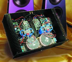
In early 1984, Elektor magazine beat the competition hands-down by publishing the design of a then-revolutionary MOSFET amplifier. Even now, this amplifier enjoys an enthusiastic following. In response to many requests, we have brought the design up to date and given some attention to improved reliability and operating safety. The output power is 90 watts into 8 ohms or 135 watts into 4 ohms, which should leave little to be desired for most users.There are surely not very many circuit designs that continue to enjoy such a high level of interest more than ten years after their original appearance, as does the Crescendo power amplifier from 1984. In part, this is due to its completely symmetrical design, which was in fact an unusual feature at that time, but unquestionably it is mainly due to the use of power MOSFETs in the output stage. A lot of people happen to be fervent fans of these devices. Even people who swear by valve amplifiers and are allergic to anything with ‘semiconductor’ in its name often have a weakness for MOSFETs, and are thus prepared to make an exception for them. Sadly enough, most of the problems with the amplifier in question had to do with the MOSFETs.
Materials
Gerber file
CAM/CAD data for the PCB referred to in this article is available as a Gerber file. Elektor GREEN and GOLD members can exclusively download these files for free as part of their membership. Gerber files allow a PCB to be produced on an appropriate device available locally, or through an online PCB manufacturing service.
Elektor recommends the Elektor PCB Service service from its business partner Eurocircuits or AISLER as the best services for its own prototypes and volume production.
The use of our Gerber files is provided under a modified Creative Commons license. Creative Commons offers authors, scientists, educators and other creatives the freedom to handle their copyright in a more free way without losing their ownership.
PCB
Component list
Amplifier board
Resistors:
R1 = 1MOhm
R2 = 47kOhm
R3,R22 = 470Ohm
R4,R5 = 1MOhm 8
R6,R7,R11,R12 = 47Ohm
R8,R9,R13,R14 = 1kOhm
R10,R15 = 330Ohm
R16,R19,R30,R31 = 22kOhm
R17,R20,R28 = 270Ohm
R18,R21 = 8kOhm 2
R23 = 12kOhm
R24,R26 = 10kOhm
R25,R27 = 33Ohm
R29 = 120Ohm
R32,R33 = 220Ohm
R34,R35 = 0Ohm 22 / 5W low-inductance, e.g., MPC71 series
R36 = 10Ohm / 1W *
R37 = 1Ohm / 5W
P1 = 1kOhm preset H
Capacitors:
C1 = 2µF2, MKT (Siemens), lead pitch 5mm or 7.5mm
C2,C4,C5 = 1nF
C3 = 180nF
C6,C7 = 100µF 25V radial
C8,C9 = 220µF 25V radial
C10,C12,C14 = 100nF
C11 = 10nF *
C13,C15 = 1000µF 63V radial
Inductors:
L1 = 9 turns 1.5 mm dia. ECW around R37, inside diameter 8 mm
Semiconductors:
D1,D2 = rectangular face, red
D3,D4 = zener diode 3V9 / 0.5W
T1,T2,T6 = BC546B
T3,T4,T5 = BC556B
T7 = BC560C
T8 = MJE350
T9 = BC550C
T10 = MJE340
T11 = 2SK537 (Toshiba)
T12 = 2SK1530 (Toshiba)
T13 = 2SJ201 (Toshiba)
Miscellaneous:
5 off M3 spade terminals, PCB mount
3 off ceramic (or mica) isolating washer for voor T8/T10/T11
2 off mica isolating washer for T12/T13 (e.g., TO-218 sheets size 21 x 24 mm)
Heatsink: <0.5° K/W (e.g., Fischer type SK47/100 mm, Dau Components)
PCB, ord3r code 010001-1
Mainsd power-on delay PCB , order code 974078-1
Enclosre, e.g., Monacor (Monarch) type UC113/SW
*) may be omitted
Protection board
Resistors:
R1,R4 = 390Ohm
R2,R5 = 120Ohm
R3,R6 = 18kOhm
R7,R9 = 1kOhm / 5W
R8,R10 = 5kOhm 6
R11,R25,R30,R31 = 10kOhm
R12,R13,R24 = 1MOhm
R14 = 150kOhm
R15 = 39kOhm
R16,R20,R21 = 220kOhm
R17 = 330kOhm
R18 = 12kOhm
R19 = 330Ohm
R22 = 15kOhm
R23 = 680Ohm
R26,R27 = 4kOhm 7
R28 = 470kOhm
R29 = 3kOhm 3
Capacitors:
C1,C2 = 150pF
C3,C4 = 22µF 63V radial
C5 = 47µF 63V radial
C6 = 2µF2 MKT (Siemens), lead pitch 5mm or 7.5mm
C7,C8
Resistors:
R1 = 1MOhm
R2 = 47kOhm
R3,R22 = 470Ohm
R4,R5 = 1MOhm 8
R6,R7,R11,R12 = 47Ohm
R8,R9,R13,R14 = 1kOhm
R10,R15 = 330Ohm
R16,R19,R30,R31 = 22kOhm
R17,R20,R28 = 270Ohm
R18,R21 = 8kOhm 2
R23 = 12kOhm
R24,R26 = 10kOhm
R25,R27 = 33Ohm
R29 = 120Ohm
R32,R33 = 220Ohm
R34,R35 = 0Ohm 22 / 5W low-inductance, e.g., MPC71 series
R36 = 10Ohm / 1W *
R37 = 1Ohm / 5W
P1 = 1kOhm preset H
Capacitors:
C1 = 2µF2, MKT (Siemens), lead pitch 5mm or 7.5mm
C2,C4,C5 = 1nF
C3 = 180nF
C6,C7 = 100µF 25V radial
C8,C9 = 220µF 25V radial
C10,C12,C14 = 100nF
C11 = 10nF *
C13,C15 = 1000µF 63V radial
Inductors:
L1 = 9 turns 1.5 mm dia. ECW around R37, inside diameter 8 mm
Semiconductors:
D1,D2 = rectangular face, red
D3,D4 = zener diode 3V9 / 0.5W
T1,T2,T6 = BC546B
T3,T4,T5 = BC556B
T7 = BC560C
T8 = MJE350
T9 = BC550C
T10 = MJE340
T11 = 2SK537 (Toshiba)
T12 = 2SK1530 (Toshiba)
T13 = 2SJ201 (Toshiba)
Miscellaneous:
5 off M3 spade terminals, PCB mount
3 off ceramic (or mica) isolating washer for voor T8/T10/T11
2 off mica isolating washer for T12/T13 (e.g., TO-218 sheets size 21 x 24 mm)
Heatsink: <0.5° K/W (e.g., Fischer type SK47/100 mm, Dau Components)
PCB, ord3r code 010001-1
Mainsd power-on delay PCB , order code 974078-1
Enclosre, e.g., Monacor (Monarch) type UC113/SW
*) may be omitted
Protection board
Resistors:
R1,R4 = 390Ohm
R2,R5 = 120Ohm
R3,R6 = 18kOhm
R7,R9 = 1kOhm / 5W
R8,R10 = 5kOhm 6
R11,R25,R30,R31 = 10kOhm
R12,R13,R24 = 1MOhm
R14 = 150kOhm
R15 = 39kOhm
R16,R20,R21 = 220kOhm
R17 = 330kOhm
R18 = 12kOhm
R19 = 330Ohm
R22 = 15kOhm
R23 = 680Ohm
R26,R27 = 4kOhm 7
R28 = 470kOhm
R29 = 3kOhm 3
Capacitors:
C1,C2 = 150pF
C3,C4 = 22µF 63V radial
C5 = 47µF 63V radial
C6 = 2µF2 MKT (Siemens), lead pitch 5mm or 7.5mm
C7,C8
Discussion (0 comments)