Article
Darkroom Timer
simple… with a PIC!
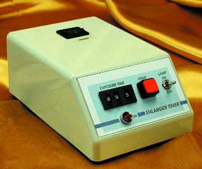
A darkroom timer is not such a complicated device: you can easily build one yourself using a microcontroller.Although previous darkroom timer designs have contained vast expanses of TTL or CMOS devices, that has all radically changed now, as can be seen in Figure 1. The circuit is controlled by a microcontroller from the PIC range. This drives an opto-triac (IC3) which switches the mains voltage from the input connector K1 to the output connector K2, and thereby turns on the enlarger lamp. The desired exposure time can be set to a resolution of 0.1 s using three thumbwheel switches. The setting is read directly from the switches in BCD format: their four outputs A-D represent the four bits of the BCD digit.
Materials
Gerber file
CAM/CAD data for the PCB referred to in this article is available as a Gerber file. Elektor GREEN and GOLD members can exclusively download these files for free as part of their membership. Gerber files allow a PCB to be produced on an appropriate device available locally, or through an online PCB manufacturing service.
Elektor recommends the Elektor PCB Service service from its business partner Eurocircuits or AISLER as the best services for its own prototypes and volume production.
The use of our Gerber files is provided under a modified Creative Commons license. Creative Commons offers authors, scientists, educators and other creatives the freedom to handle their copyright in a more free way without losing their ownership.
PCB
Component list
Resistors:
R1 =4 x 10kOhm SIL array
R2 =10kOhm
R3 =1kOhm 5
R4 =330Ohm
Capacitors:
C1-C4 =47nF
C5 =470µ F 16V radial
C6 =220µ F 16V radial
C7 =100nF
Semiconductors:
D1-D4 =1N4001
D5-D16 =1N4148
D17 =LED, red, high efficiency
IC1 =7805
IC2 =PIC16F84-04/P (order code 000182-41)
IC3 =S201S01 (Sharp) (Conrad # 16 81 65)
Miscellaneous:
K1,K2 =2-way PCB terminal block, 7.5 mm lead pitch
F1 = fuse, 0.5 AT (time lag), with PCB-mount holder
TR1 =Mains transformer 6 V, 1.5 VA (Conrad Electronics # 50 60 44)
S1,S2,S3 =BCD-encoded thumbwheel switch type PICO (Conrad 70 10 84)
2 spacers (Conrad Electronics # 70 11 06)
1 pair end cheeks (Conrad Electronics #70 11 33)
X1 =4 MHz resonator (Conrad Electronics # 50 31 69-55)
S4 = pushbutton, 1 make contact
S5 =SPDT changeover switch
Case: Teko 362 (Conrad Electronics # 52 39 68)
PCB, order code 000182-1
Disk, source and object code, order code 000182-11
Discussion (0 comments)