Article
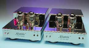
PPP HiFi Valve Power Amplifier
using KT88 valves

Thanks to their pleasant sound, valve-type power amplifiers continue to enjoy uninterrupted popularity. With such an amplifier, you can eliminate the impression of coldness, sterility and artificiality that many people experience with CDs.The design for a power amplifier that is presented in this article is based on the PPP principle. PPP stands for ‘Parallel Push-Pull’. ‘Push-pull’ means that the output stage is composed of two active elements acting in phase opposition. One of the valves handles the positive half-cycles, while the other one handles the negative half-cycles. In a Parallel Push-Pull configuration, the valves in the output stage are connected in parallel with respect to the ac signal. The disadvantage is that the power efficiency per valve pair is less than with classical Class AB push-pull operation. Otherwise the PPP principle has only advantages. This output stage configuration was invented in the early 1950s, and it was the configuration of choice in studios. Reduced distortion, good sound and a wide frequency response were more important in this application area than high power efficiency. With the triumphal march of semiconductor technology, PPP was unable to retain any significant territory, due to its relatively low power efficiency and relatively high price. However, with the aid of modern resources it is possible to construct excellent HiFi PPP power amplifiers at an acceptable price.
Component list
Power Output Stage
with KT 88 or 6550A
Resistors:
(unless otherwise stated, use metal film types, 0.7W, 1% tolerance; MO = Metal oxide, 5% tolerance)
R1,R2 = 68kOhm
R3 = 2kOhm 2
R4 = 150kOhm , MO, 2W
R5 = 2kOhm 7, MO 2W
R6 = 2kOhm 2
R7 = 1MOhm
R8 = 2kOhm 7
R9 = 22kOhm , MO, 2W
R10 = 390kOhm
R11,R12 = 47kOhm , MO, 2W
R13 = 2kOhm 7, MO, 2W
R14 = 33kOhm
R15,R16 = 10kOhm , MO, 2W
R17,R18 = 10kOhm
R19,R20 = 220kOhm
R21,R22 = 33kOhm
R23,R24 = 3kOhm 3
R25,R26 = 10Ohm , MO, 2W
R27,R28 = 270Ohm , MO, 2W
R29,R30 = 47Ohm
P1,P2 = preset 25kOhm
Capacitors:
C1 = 2µ F2 50V bipolar
C2 = 10pFceramic
C3 = 100pF ceramic
C4,C5 = 47µ F 450V axial
C6 = 10-33pF (fit only if parasitic oscillation is noticed)
C7,C8,C9 = 0µ F22 630V, MKS 4
C10 = 10µ F 100V, lead pitch 5mm
C11-C14 = 47µ F 100V, lead pitch 5mm
C15 = 1nF, MKH, lead pitch 7.5mm (see text)
Semiconductors:
D1 = zener diode 56V 1.3W
D2-D4 = zener diode 110V 1.3 W
D5,D6 = 1N4007
Miscellaneous:
V1 (Rö1) = ECC83
V2 (Rö2) = ECC81
V4 (Rö4),V5 (Rö5) = KT88 or 6550 A
Tr1 (Ü1) = E-1220 (if necessary)
Tr2 (Ü2) = AP-234
2 off 'Noval' (9-way) valve socket, PCB mount
2 off 'Octal' valve socket, PCB mount
Tr1 = Mains transformer NTR-P\7 (Mono) or NTR-P\5 (Stereo)
COMPONENTS LIST
Power Output Stage with EL 34
Resistors:
(unless otherwise stated, use metal film types, 0.7W, 1% tolerance; MO = Metal oxide, 5% tolerance)
R1,R2 = 68kOhm
R3 = 2kOhm 2
R4 = 150kOhm , MO, 2W
R5 = 2kOhm 7, MO, 2W
R6 = 2kOhm 2
R7 = 1MOhm
R8 = 2kOhm 7
R9 = 47kOhm , MO, 2W
R10 = 220kOhm
R11,R12 = 47kOhm , MO, 2W
R13 = 2kOhm 7, MO, 2W
R14 = 33kOhm
R15,R16 = 10kOhm , MO, 2W
R17,R18 = 22kOhm
R19,R20 = 220kOhm
R21,R22 = 33kOhm
R23,R24 = 10kOhm
R25,R26 = 10Ohm , MO, 2W
R27,R28 =150Ohm , MO, 2W
R29,R30 = 47Ohm
P1,P2 = preset 25 kOhm
Capacitors:
C1 = 2µ F2 50


Discussion (0 comments)