Article
DCI PLC
a computer-simulated PLC
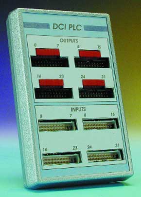
PLCs are microcontroller circuit boards that are frequently used in a wide variety of industrial control and automation applications. The PLC described here is implemented in software. A complete PLC is simulated on a standard Windows PC. Using an external connection box, the PC can also sense and control many kinds of real items.The abbreviation ‘PLC’ stands for ‘Programmable Logic Controller’. These devices are also sometimes referred to as ‘freely programmable controllers’ in the trade. This term refers to an electronic circuit that can be used to automate machinery and processes. A PLC thus can replace a conventional relay logic circuit.A PLC always consists of a CPU module and several digital input and output modules. The number of input and output modules depends on the size of the process to be controlled.One of the major advantages of a PLC is that it makes it very easy to extend or modify the process. Consequently, PLCs have for years been an indispensable element in the automation of industrial systems.
Materials
Gerber file
CAM/CAD data for the PCB referred to in this article is available as a Gerber file. Elektor GREEN and GOLD members can exclusively download these files for free as part of their membership. Gerber files allow a PCB to be produced on an appropriate device available locally, or through an online PCB manufacturing service.
Elektor recommends the Elektor PCB Service service from its business partner Eurocircuits or AISLER as the best services for its own prototypes and volume production.
The use of our Gerber files is provided under a modified Creative Commons license. Creative Commons offers authors, scientists, educators and other creatives the freedom to handle their copyright in a more free way without losing their ownership.
PCB
Component list
Resistors:
R1-R7 = 10kOhm
R4-R7 = SIL array 8 x 10kOhm
R8-R11 = SIL array 8 x 1kOhm
Capacitors:
C1-C16, C18,C19 = 100nF
C17 = 100µ F 25V radial
C20 = 10µ F 25V radial
Semiconductors:
D1,D2,D3 = zener diode 4.7 V 400mW
D4 = 1N4001
D5-D36 = LED, rectangular, red, high efficiency
IC1-IC4 = 4021
IC5-IC8 = 74HCT4094
IC9 = 7805
Miscellaneous:
K1 = 9-way sub-D socket (female), PCB mount
K2-K9 = 20-way boxheader
Case: Teko 160x95x45 mm (Conrad Electronics #526177)
PCB, order code 000163-1 (see Readers Services page)
Disk, Windows program, order code 000163-11
Discussion (0 comments)