Article
Vehicle Adapter for Notebook PCs
19 volts from a car battery
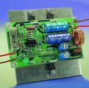
Notebook PCs are great but stray too far from a source of power and it’s not long before low-battery warnings start to appear. Mains adapters come as standard but car adapters are expensive accessories. Good enough reason to get the soldering iron out!Designs for switchmode power supplies or inverters always pose a problem for home constructors because they usually include inductive elements, transformers, chokes or ferrite cores that are difficult to procure. This dc-to-dc converter design uses just one standard inductor. In the prototype this inductor was part of the notebook’s existing supply lead, here it is built onto the PCB.This adapter design is suitable for notebooks requiring a dc input voltage in the range of 14 V to 19 V. It can provide a continuous current of 2 A with short duration peaks of around 2.5 A. The efficiency of the design is in the order of 60 to 80 % depending on the output voltage and current. A big advantage of this design is its low quiescent current of only 75 mA (more on this later).
Materials
Gerber file
CAM/CAD data for the PCB referred to in this article is available as a Gerber file. Elektor GREEN and GOLD members can exclusively download these files for free as part of their membership. Gerber files allow a PCB to be produced on an appropriate device available locally, or through an online PCB manufacturing service.
Elektor recommends the Elektor PCB Service service from its business partner Eurocircuits or AISLER as the best services for its own prototypes and volume production.
The use of our Gerber files is provided under a modified Creative Commons license. Creative Commons offers authors, scientists, educators and other creatives the freedom to handle their copyright in a more free way without losing their ownership.
PCB
Component list
Resistors:
R1,R2 = 10kOhm
R3 = 560Ohm
R4,R11,R12 = 3kOhm 3
R5,R7,R8 = 1kOhm 5
R6,R9 = 6kOhm 8
R10 = 220Ohm , 1W
R13 = 1kOhm 8
R14 = 15kOhm
R15,R17 = 680Ohm
R16 = 150Ohm , 5W
R18 = 820Ohm
Capacitors:
C1 = 5nF6
C2 = 2200µF 16V axial
C3 = 470µF 63V axial
C4,C5 = 470µF 16V radial
C6 = 10µF 16V
Semiconductors:
D1 = 1N4148
D2,D3 = MBR745
D4 = zener diode 6V8 0.4W
D5 = zener diode 12V 0.4W
D6 = LED, high efficiency
IC1 = TLC272CP
T1,T5 = BC337-40
T2 = BDX53B
T3,T4 = BD912
Miscellaneous:
F1 = fuse, 4A, time lag, with PCB mount holder
L1 = 50µH 3A suppressor coil (SFT830D, Conrad Electronics #534412)
Metal enclosure, size 119x 65x 39 mm
2 heatsinks
12V miniature fan (Conrad Electronics #532614)
Discussion (0 comments)