Article
Induction Radio
a nostalgic listening experience

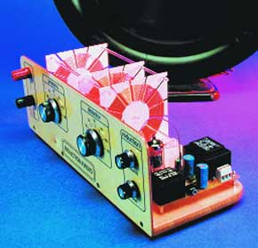
This radio is a sight for sore eyes. The magnificent coils, the gleaming valve and the striking wooden chassis suggest that this is a collector’s item from the early days of radio. But appearances can be deceptive. This radio can be constructed easily at home and offers good reception across the medium-wave band.In the period between 1930 and 1960 building your own radio receiver was a very popular pastime. In those early days of radio you had to make nearly everything yourself, but after the increase in broadcasting stations more of the components could be found ready-made. Since then, the construction of a crystal set or single-valve receiver became a piece of cake. You saved your pennies until you had enough money, bought all the bits and constructed the receiver according to one of the many tried and tested designs.These days, if you try to build a simple valve based medium wave radio you soon hit a brick wall. All those trusted components of the past are hardly available anymore. The supply transformer, output transformer, medium wave coil, tuning capacitor — try finding them. The radio described in this article turns a need into a virtue. It is a combination of old and new. The radio is built along an old design, but using modern components. The components are widely available and the construction really is simple.
Component list
Resistors:
R1,R4 = 1M?
R2 = 68k?
R3 = 10k?
R5 = 2k?2
R6 = 470?
R7 = 68? 1W
R8 = 150? 0.5W
P1 = 1k? linear potentiometer
P2 = 10k? linear potentiometer
Capacitors:
C1,C3 = tuning capacitor, flat models, 500pF, (e.g., Conrad Electronics # 482323, Display Electronics (Holland) # 02.84.500p
C2,C4,C5,C6,C8 = 100pF polystyrene or polypropylene (e.g., Conrad Electronics # 458686)
C7 = 10nF, MKT (Siemens), lead pitch 7.5 or 10mm
C9 = 500pF (470pF) polystyrene or polypropylene (e.g., Conrad Electronics # 458767)
C10 = 100nF, MKT (Siemens), lead pitch 7.5 or 10mm
C11,C12 = 470µF 63V
Inductors:
LA,LD,LR = see inset
Miscellaneous:
D1 = 1N4001
V1 = ECC82
T1 = mains transformer, secondary 9V 1.5VA, e.g., Gerth # 3109-1, Display Electronics (Holland) # 02.10.159.091
T2 = mains transformer, secondary 2x18V 4.8 VA, e.g., Gerth # 421.36-2, Display Electronics (Holland) # 02.10.459.362
K1 = stereo headphones socket, 3.5 mm, PCB mount
K2 = PCB terminal block, lead pitch 10mm
Socket, noval, 9-pin, for ECC82
Binding post (red) for antenna wire
Binding post (black) for earth connection
2 pointer knobs, 15 x 33 mm, for 6mm spindle
2 pointer knobs, 13 x 20 mm, for 6mm spindle
Mans cord
Headphones, 32?


Discussion (0 comments)