Article
Remote Process Control using a Mobile Phone (2)
programming and use
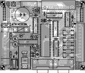
The SMS Chip checks incoming text for a password, switches outputs interactively or at preset times, controls an LCD and sends status information back to any mobile phone.In the first part of this article we looked at the circuit design and hardware for this project and now we turn our attention to the PCB layout, the software and the text message structure.A look at the component placement diagram in Figure 1 shows that you will not need any special soldering skills to complete the circuit board. No wire links are required and all the ICs (except the voltage regulator) are fitted into sockets. All external connections are made via pinheaders or connectors mounted around the edge of the PCB. The LED arrays D1 and D2 can be replaced by groups of eight individual LEDs but if you use high-efficiency types it will be necessary to substitute 1 k? or 1.5 k? resistor networks for R1 and R2. In all cases it will still be necessary to use the ACT type buffer specified in the parts list for IC3 and IC4.
Materials
Gerber file
CAM/CAD data for the PCB referred to in this article is available as a Gerber file. Elektor GREEN and GOLD members can exclusively download these files for free as part of their membership. Gerber files allow a PCB to be produced on an appropriate device available locally, or through an online PCB manufacturing service.
Elektor recommends the Elektor PCB Service service from its business partner Eurocircuits or AISLER as the best services for its own prototypes and volume production.
The use of our Gerber files is provided under a modified Creative Commons license. Creative Commons offers authors, scientists, educators and other creatives the freedom to handle their copyright in a more free way without losing their ownership.
PCB
Component list
Resistors:
R1,R2 = 8-way 330Ohm SIL array
R3 = 1kOhm 5
R4 = 1kOhm 8
R5 = 4kOhm 7
P1 = 10kOhm preset
Capacitors:
C1, C2, C4,C5,C6 = 100nF (5mm lead pitch)
C3 = not fitted
C7,C8 = 27pF
C9 = 10µF 63V radial
C10 = 100µF 25V radial
C11-C15 = 1µF 16V radial
C16 = 100µF 10V radial
Semiconductors:
D1,D2 = LED, 3mm (8 pcs) or array *
D3, D4 = LED, green, high efficiency
D5 = 1N4002
D6 = BAT48
D7 = 1N4148
IC1 = AT89(L)S8252-24PC in DIP40 case. Programmed, available from Engelmann&Schrader
IC2 = 74HCT573
IC3,IC4 = 74ACT240*
IC5 = GAL16V8, programmed, Publishers' order code 010087-31
IC6 = RTC72421
IC7 = MAX207 or ADM207EAN
IC8 = 7805 with ICK35SA heatsink *
Miscellaneous:
BT1 = CR2032 Lithium button cell with PCB mount holder
F1 = fuse, 1A, slow, with PCB mlunt holder
JP1-JP5 = jumper
K1 = 8-way PCB terminal block, lead pitch 5mm
K2 = 12-way PCB terminal block
K3,K4 = 9-way sub-D plug (male), PCB mount, angled pins *
K5 = 26-way boxheader, angled pins
K6 = 14-way boxheader
K7 = 2-way PCB terminal block, lead pitch 5mm
K8 = mains adaptor socket, PCB mount
RE1 = not fitted
RE2-RE5 = 5V PCB mount relay, 1 make or 1 changeover contact, with flyback diode (e.g., Meder 1A72-12D 5V or Siemens V23100-V4305-C010 or Conrad Electronics #504580) *
S1,S2,S3 = pushbutton with 1 make contact
S4 =switch, on/off *
X1 = 11.0592MHz quartz crystal
LC Display = alphanumeric display with HD44780 controller (or compatible), e.g., 4 lines of 20 characters
PCB, Publishers' order code 010087-1
Disk, project software, Publishers' order code 010087-11
Battery eliminator (mains adaptor) 9V / 1A
* See text
Discussion (0 comments)