Article
RS232-to-RS485 Half-Duplex Adapter
advantages of balanced lines

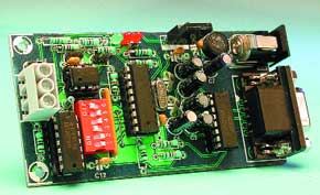
This project has been designed to interface an EIA-232 channel to an EIA-485 half-duplex bus. We should do so because EIA-485 offers more features than 232, especially where we apply a long distance wired communication involving more than two devices.The EIA-232 standard, formerly known as RS-232, was introduced about thirty years ago, well before the first application of desktop sized personal computers. The RS-232 standard mainly covers the communication between DTEs and DCEs, where DTEs are Data Circuit Terminating Equipments, and DCEs are Data Communication Equipments. A typical DTE could be just a video terminal, a printer, or even a personal computer — it can operate either as a source or destination of data, hence it is the equipment where the communication is terminated.
Materials
Gerber file
CAM/CAD data for the PCB referred to in this article is available as a Gerber file. Elektor GREEN and GOLD members can exclusively download these files for free as part of their membership. Gerber files allow a PCB to be produced on an appropriate device available locally, or through an online PCB manufacturing service.
Elektor recommends the Elektor PCB Service service from its business partner Eurocircuits or AISLER as the best services for its own prototypes and volume production.
The use of our Gerber files is provided under a modified Creative Commons license. Creative Commons offers authors, scientists, educators and other creatives the freedom to handle their copyright in a more free way without losing their ownership.
PCB
Component list
Resistors:
R1,R2,R3 = 1kOhm
R4 = 10kOhm 8-way or 6-way SIL array
R5,R6 = 100Ohm
R7,R8,R9 = 10kOhm
R10 = 120Ohm
R11,R13 = 680Ohm
R12 = 100Ohm
Capacitors:
C1,C2 = 22pF
C3-C6 = 1µ F 16V radial
C7 = 22µ F 16V radial
C8,C9,C11,C12,C13 = 100nF
C10 = 10µ F 16V radial
Semiconductors:
D1,D2,D3 = LED, red, low current
IC1 = PIC16C54-HS/P, programmed, order code 020003-41
IC2 = MAX232CP
IC3 = 74HCT00
IC4 = 75176BP
IC5 = 7805
B1 = bridge rectifier B40C800, round case (40V piv, 800mA)
Miscellaneous:
JP1,JP2,JP3 = jumper
K1 = 9-way sub-D socket (female), angled pins, PCB mount
K2 = mains adaptor socket, PCB mount
K3 = 3-way PCB terminal block, lead pitch 5mm
S1 = 6-way DIP-switch
X1 = 4MHz quartz crystal


Discussion (0 comments)