Article
Telephone Baby Monitor
cut through the static
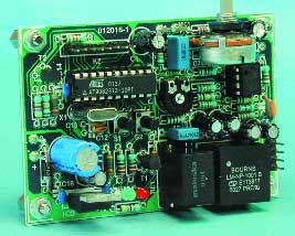
The usefulness of baby monitor alarms using (FM) radio has always been limited by poor range and its susceptibility to interference. This novel design uses a microcontroller to take a fresh look at the problem.There are several different types of baby monitor on the market. The most common provides a short-range radio link (typically 100 m) between the transmitter unit in the nursery and the receiver unit carried by a parent. Another type uses audio to modulate a carrier frequency sent along mains wiring to the parents receiver plugged into a mains outlet. The RF model has a limited range and the mains modulation method requires that the parent cannot wander too far from a mains socket. Both systems are susceptible to interference.
Materials
Gerber file
CAM/CAD data for the PCB referred to in this article is available as a Gerber file. Elektor GREEN and GOLD members can exclusively download these files for free as part of their membership. Gerber files allow a PCB to be produced on an appropriate device available locally, or through an online PCB manufacturing service.
Elektor recommends the Elektor PCB Service service from its business partner Eurocircuits or AISLER as the best services for its own prototypes and volume production.
The use of our Gerber files is provided under a modified Creative Commons license. Creative Commons offers authors, scientists, educators and other creatives the freedom to handle their copyright in a more free way without losing their ownership.
PCB
Extra info / Update
In the circuit diagram, the value of C8 should be corrected to read 470 pF.
Component list
Resistors:
R1,R4 = 10k?
R2 = 8k?2
R3 = 2k?2
R5 = 100?
R6 = 220k?
R7,R24 = 47?
R8,R10 = 1k?5
R9,R13,R14 = 100k?
R11 = 15k?
R12,R22 = 33k?
R15 = 1k?
R16 = 560?
R17,R18 = 220?
R19,R20 = 4k?7
R21 = 47k?
R23 = 180k?
P1 = 10k? preset H
P2 = 22k? potentiometer, linear, mono, miniature version
Capacitors:
C1 = 680nF
C2 = 68pF
C3 = 47µF 25V radial
C4 = 220µF 10V radial
C5,C6,C10 = 1µF 63V radial
C7,C14,C15,C16,C18 = 100nF ceramic
C8 = 470pF
C9,C17 = 10µF 63V radial
C11 = 470nF
C12,C13 = 22pF
C19 = 470µF 25V radial
Semiconductors:
D1 = LED, red, 3mm
D2 = LED, green, 3mm
D3 = 1N4148
D4 = zener diode 12V 1.3W
D5 = 1N4002
T1 = BC547B
T2 = BC557B
IC1 = AT90S2313-10PC, programmed, order code 012016-41
IC2 = TS922IN (Farnell)
IC3 = 7805
Miscellaneous:
K1 = 4-ay SIL header
K2 = 8-way SIL header
S1,S2 = pushbutton, 6x6 mm
Re1 = subminiature relay 16x119x11.5 mm with SPDT contact, e.g., Maluska FRS1B-S DC 5V, (5 V, 56 ?, Conrad Electronics # 505188)
X1 = 10MHz quartz crystal (Cload = 32pF, parallel resonance)
Tr1 = line transformer, Bourns LMNP-1001 B)
MIC1 = electret Microphone element (e.g., Monacor/Monarch MCE2000)
PCB, order code 012016-1
Disk, C source code and hex files, order code 012016-11
Discussion (0 comments)