Article
Capacitance Meter
using a CMOS timer
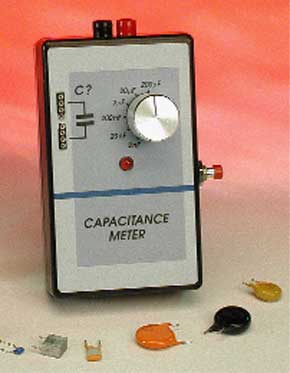
As demonstrated in this article, a simple test instrument is sufficient to unravel the mysteries of the cryptic and impossibly small print often found on capacitors.Besides the obvious advantages of space savings, the miniaturisation of electronic components has a couple of dark sides too. Until about ten years ago, there used to be plenty of room on capacitor bodies to print the capacitance value, the tolerance, operating voltage, manufacturer code and other salient information. Today’s capacitors, being much smaller in size, have illegible, incredibly small and cryptic print on them and before fitting such a capacitor you are well advised to measure the actual capacitance! Rocket science? Well, no. The good news is that this article describes a low-cost and extremely simple instrument to do just that.
Materials
Gerber file
CAM/CAD data for the PCB referred to in this article is available as a Gerber file. Elektor GREEN and GOLD members can exclusively download these files for free as part of their membership. Gerber files allow a PCB to be produced on an appropriate device available locally, or through an online PCB manufacturing service.
Elektor recommends the Elektor PCB Service service from its business partner Eurocircuits or AISLER as the best services for its own prototypes and volume production.
The use of our Gerber files is provided under a modified Creative Commons license. Creative Commons offers authors, scientists, educators and other creatives the freedom to handle their copyright in a more free way without losing their ownership.
PCB
Component list
Resistors:
R1 = 390?
R2 = 22M?
R3 = 2M?2
R4 = 220k?
R5,R9 = 22k?
R6 = 2k?2
R7 = 220?
R8 = 1k?
P1 = 2M?5 preset
P2 = 25k? preset
Capacitors:
C1,C2,C4 = 100nF
C3 = 10µF 63V radial
C5 = 47µF 16V radial
Semiconductors:
D1,D3 = zener diode 5V6, 500mW
D2 = LED, red, high-efficiency (2mA)
T1 = BF245A or BF256A
IC1,IC2 = 555C or TLC555 (CMOS 555)
Miscellaneous:
S1 = rotary switch, 2 poles, 6 positions
S2 = pushbutton, 1 make contact
K1,K2 = 4-way SIL socket for IC pins, turned pins
Case, 60 x 10 x 126 mm with battery compartment
Knob
Moving coil meter, f.s.d.100 µA
Discussion (0 comments)