Article
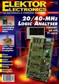
20/40 MHz Logic Analyser
with expansion capability and PC control
With analogue electronics, an oscilloscope is usually sufficient for solving any problems encountered during development or troubleshooting. With digital electronics, things are not so simple. It is often necessary to observe several different logic levels at the same time, and on top of that, high working frequencies are quite common. A logic analyser is clearly the proper tool in such a situation.A normal oscilloscope is not particularly suitable for working with circuits containing microprocessors, DSPs or other digital components. The bandwidth is usually too small for the extremely fast signals used with such components. Furthermore, it is usually not possible to view more than two signals at once (in the best case, four signals can be viewed). Also, an analogue oscilloscope can only measure repetitive signals, which is not very helpful with digital signal streams.
Materials
Extra info / Update
The parts list and the circuit diagram should be amended to read:IC8,IC9 = 74F393 or 74LS393IC11 = 74LS688IC13 = 74F573 or 74LS573These components will work in the 20 and 40 MHz version.
Component list
Resistors:
R1-R4 = 470k
R5-R8 = 8-way 470k SIL array
R9 =1k2
R10 = 10k
R11 = 47k
Capacitors:
C1-C7,C14-C23,C28,C29 = 47nF
C8,C9 = 22pF
C10-C13 = 1µF 16V radial
C24 = 2200µF 16V radial
C25,C26 = 100nF
C27 = 1µF 16V radial
Semiconductors:
B1 = B80C1500 in rectangular case, (80V piv, 1.5A)
D1 = LED, red, low-current
IC1-IC4 = IDT7206 (-15, etc. see text) or CY7C425-15PC
IC5 = 74F74
IC6 = 74F00
IC7 = 74F02
IC8,IC9 = 74F393
IC10,IC12 = 74F251
IC11 = 74F688
IC13 = 74LS573
IC14 = 74F153
IC15 = MAX232
IC16 = AT90S8515-8PC, programmed, order code 020032-41
IC17 = 7805
IC18 = TL7705-ACP
IC19 = 40MHz or 20MHz oscillator module in DIL14 case (see text)
Miscellaneous:
K1-K4 = 2-way boxheader (angled pins possible)
K5 = 9-way sub-D socket (female), PCB mount, angled pins
X1 = 8MHz quartz crystal
PB, order code 020032-1
Disk, demo program, order code 020032-11 or Free Download
Discussion (0 comments)