Article
Rev Counter for R/C Models
Using an optical sensor
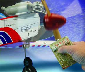
The engines used in modelling have to be carefully tuned if they are to run at their best. An important measurement is the engine speed at full power. This circuit can be used for such measurements, as long as a propeller is driven or a marker line is visible.If you want to obtain the best performance from a model engine, it is essential that the engine speed can be measured accurately. With the help of a good rev counter the carburettor can be adjusted correctly at full power and engines can be compared with each other. This can become quite complicated, since the type of propeller, fuel, glow plug, etc, all affect the maximum engine speed.
Materials
Gerber file
CAM/CAD data for the PCB referred to in this article is available as a Gerber file. Elektor GREEN and GOLD members can exclusively download these files for free as part of their membership. Gerber files allow a PCB to be produced on an appropriate device available locally, or through an online PCB manufacturing service.
Elektor recommends the Elektor PCB Service service from its business partner Eurocircuits or AISLER as the best services for its own prototypes and volume production.
The use of our Gerber files is provided under a modified Creative Commons license. Creative Commons offers authors, scientists, educators and other creatives the freedom to handle their copyright in a more free way without losing their ownership.
PCB
Extra info / Update
A 4.7 kOhm resistor should be inserted between pin 7 of IC1 and the base of T4. Without the series resistor, the comparator output is short-circuited to ground by way of the base-emitter junction of T4. The resulting current will however not damage the TLC272.
Component list
Resistors:
R1 = 390?
R2,R3,R6,R9,R11,R12,R53,R54 = 1k?
R4 = 5k?6
R5,R10 = 10k?
R7 = 1k?5
R8 = 22k?
R13-R52 = 680?
Capacitors:
C1 = 220µF 16V radial
C2,C3,C6-C14 = 100nF
C4,C5 = 22pF
C15 = 10µF 16V radial
Semiconductors:
D1 = zener diode 1.4V 500mW
D2 = IR LED (e.g., LD271)
IC1 = TLC272CP
IC2 = 89C2051-12PC, programmed, order code 024111-41
IC3,IC4,IC6,IC7,IC8 = 74HCT4094
IC5 = 74HC04
IC9 = 7805
LD1-LD5 = HD1133 O-K
T1 = BPW40
T2 = BC557
T3,T4 = BC547
Miscellaneous:
K1 = 9-V battery clip
S1,S2,S3 = pushbutton, 1 make contact
X1 = 12MHz quartz crystal
Enclosure: Bopla EG1530B
PCB, order code 024111-1
Disk, contains source- and hex code, order code 024111-11
Discussion (0 comments)