Article
FM Remote Control Receiver
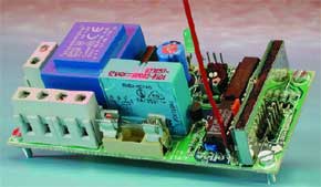
It is often required to switch electrical appliances from a distance (the garage light, when you’re still in your car for example) without there being a direct line of sight between the transmitter and receiver. This rules out the use of infrared, so we have to use radio signals instead. An ideal solution for this application is provided by transmitter and receiver modules, which operate at a frequency of 433 MHz and are available ready-made.
Gerber file
CAM/CAD data for the PCB referred to in this article is available as a Gerber file. Elektor GREEN and GOLD members can exclusively download these files for free as part of their membership. Gerber files allow a PCB to be produced on an appropriate device available locally, or through an online PCB manufacturing service.
Elektor recommends the Elektor PCB Service service from its business partner Eurocircuits or AISLER as the best services for its own prototypes and volume production.
The use of our Gerber files is provided under a modified Creative Commons license. Creative Commons offers authors, scientists, educators and other creatives the freedom to handle their copyright in a more free way without losing their ownership.
PCB
Component list
Resistors:
R1-R4 = 1k?
R5 = 47k?
R6,R7,R8 = 10k?
P1 = 25k? preset
Capacitors:
C1,C2,C3= 100nF ceramic
C4 = 4µF7 63V radial
C5 = 470µF 25V radial
C6-C9 = 47nF ceramic
Semiconductors:
D1 = 1N4148
D2 = LED, high-efficiency
T1 = BC547B
IC1 = R5-434-5-20 from R.F. Solutions (Farnell # 352-4383)
IC2 = HT12F from Holtek
(Maplin)
IC3 = 74HC74
IC4 = 78L05
Miscellaneous:
JP1 = 3-way pinheader with
jumper
K1 = 5-way pinheader
K2 = 3-way pinheader
K3,K4,K5 = 2-way PCB terminal block, lead pitch 7.5 mm
S1,S2 = solder links
B1 = B80C1500 (rectangular case) (80V piv, 1.5A)
TR1 = mains transformer, 9V/1.5VA, e.g., Block type EI30-X6/4001/112 VV1109
F1 = fuse, 1AT (time lag), with PCB mount holder
RE1 = V23057-B0002-A101 vertical card relay 12 V/330 ?/ 8 A
PCB, order code 034044-1 (transmitter and receiver)
Discussion (0 comments)