Article
Voltage & Continuity Tester
for direct and alternating voltages up to 60 V

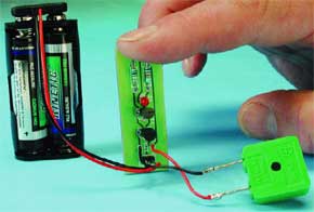
Unless it reaches really high levels, what we refer to as ‘voltage’ is totally invisible, so test and measurement equipment is a must in every electronics lab. However, in many cases you’ll just want to know if a voltage is present at or not a certain point. The tester described as this month’s Mini Project is an unusual one because it can work with just one test lead — all you have to do is use the single probe to touch the point you want to check.So where’s the other test lead connected to, after all, a voltage always exists between two points? The answer is: the voltage is measured against ‘ground’ connected to the metal enclosure of the test instrument. In this way, it is defined by the person holding the test probe in his/her hand. With each voltage test, a safe current of just a few micro-amperes flows through the person’s body. The tester will amplify this current to a level where it can be indicated by an LED.
Materials
Gerber file
CAM/CAD data for the PCB referred to in this article is available as a Gerber file. Elektor GREEN and GOLD members can exclusively download these files for free as part of their membership. Gerber files allow a PCB to be produced on an appropriate device available locally, or through an online PCB manufacturing service.
Elektor recommends the Elektor PCB Service service from its business partner Eurocircuits or AISLER as the best services for its own prototypes and volume production.
The use of our Gerber files is provided under a modified Creative Commons license. Creative Commons offers authors, scientists, educators and other creatives the freedom to handle their copyright in a more free way without losing their ownership.
PCB
Component list
Resistors:
R1 = 1MOhm
R2 = 1kOhm
Semiconductors:
D1 = LED, low current, red
T1,T2 = BC547C, BC548C or BC549C
Miscellaneous:
BZ1 = miniature piezo transducer (passive)
K1 = 2-way pinheader, lead pitch 2.5mm (0.1 in) or two solder pins
S1 = single-pole changeover switch (optional, see text)
Battery holder for two LR03 (AAA) or LR6 (AA) batteries
Enclosure: suitable metal tube (see text)
PCB, available from The PCBShop


Discussion (0 comments)