

High-End-Preamp, Part 2
This is a MEMBER ONLY article. You need a subscription to read this article.
- Unlimited access to online Member Only articles
- 3 new editions Elektor Magazine (digital)
- More than 5000 Gerber files
- 20% member discount on e-books (at elektor.com)
- 10% member discount on Products (at elektor.com)
Available from €5.33 per month.
What is Members Only
Elektor is committed to providing high-quality content on electronics, catering to tens of thousands of paying members. As part of this commitment, Elektor has launched Premium, an initiative that offers exclusive online articles to members sometimes even before they appear in the magazine.
Every day, members can access in-depth articles that showcase the best of Elektor's premium content.
This initiative aims to reward members with early access. Once logged in, members can easily enjoy this exclusive content and engage in discussions about featured projects. While Premium adds to the existing resources available, Elektor will continue to provide a wealth of free information.
Join the Elektor community today to take advantage of Premium and other benefits!
Materials
Gerber file
CAM/CAD data for the PCB referred to in this article is available as a Gerber file. Elektor GREEN and GOLD members can exclusively download these files for free as part of their membership. Gerber files allow a PCB to be produced on an appropriate device available locally, or through an online PCB manufacturing service.
Elektor recommends the Elektor PCB Service service from its business partner Eurocircuits or AISLER as the best services for its own prototypes and volume production.
The use of our Gerber files is provided under a modified Creative Commons license. Creative Commons offers authors, scientists, educators and other creatives the freedom to handle their copyright in a more free way without losing their ownership.
Component list
Resistors:
R1 = 27Ohm
R2,R9 = 47kOhm
R3 = 8-way 10kOhm SIL array
R4 = 4-way 10 kOhm SIL array
R5 = 1kOhm 5
R6,R7,R8,R10 = 10kOhm
P1 = 10kOhm preset
P2 = 100Ohm preset
Capacitors:
C1,C2,C3,C20 = 10µF 25V radial
C4-C11,C14,C15= 100nF
C12,C13 = 27pF
C16,C17,C18 = 2200µF 25V radial
C19 = 100nF ceramic, lead pitch 5mm
Semiconductors:
D1 = low-current LED (+ 2-way pinheader)
D2.,D3,D4 = zener diode 5V6, 1.3W
IC1 = PIC18LF452-I/L (PLCC). Blank ICs: Farnell # 400-9654. Programmed ICs: order code 020046-41
IC2 = PGA2311PA from Texas Instruments/Burr-Brown or CS3310 from Cirrus Logic (Crystal)
IC3 = SFH5110 (TSOP1836) (+ 3-way pinheader)
IC4,IC6 = 7805
IC5 = 7905
T1 = BC550C
Miscellaneous:
JP1,JP3 = 2-way pinheader + jumper
JP2 = wire link
K1 = 3-way PCB terminal block, lead pitch 5mm
K2 = = 2-way PCB terminal block, lead pitch 5mm
K3 = 16-way pinheader
K4 = 10-way boxheader, vertical
K5 = 26-way boxheader, vertical
X1 = 10MHz quartz crystal
12 solder pins
External parts:
LCD, 2x16 characters with backlight
12 pushbuttons for chassis mounting
2 Cinch sockets for chassis mounting, isolated and gold-plated
Mains on/off switch, chassis mount
IEC mains appliance socket, chassis mount
Disk, hex and source code files, order code 020046-11 or Free Download.
COMPONENTS LIST
(relay board, 020046-2)
Resistors:
R1-8 = 10kOhm
R9-R16 = 47kOhm
Semiconductors:
D1-D8 = 1N4004
D9-D16 = low-current LED
T1-T8 = BC550C
Miscellaneous:
JP1 = 2- way pinheader + jumper
JP2,JP3 = wire link
K1 = 10-way boxheader, vertical
K2 = 2-way PCB terminal block, lead pitch 5mm
RE1-RE8 = RY5W-K (Takamisawa), Conrad Electronics # 502852 (5V/167Ohm )
16 Cinch sockets for chassis mounting, isolated and gold-plated
COMPONENTS LIST
(asymmetrical PSU, 020046-3)
Resistors:
R1 = 0Ohm 1 5W
Capacitors:
C1-C4
Discussion (0 comments)
Vladan Savic 3 years ago
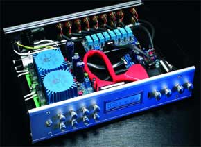
Anyway, it is obviously that project is finished and looks good