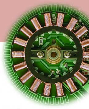
First Steps
Everything you need to know to drive a stepper motor

This is a MEMBER ONLY article. You need a subscription to read this article.
- Unlimited access to online Member Only articles
- 3 new editions Elektor Magazine (digital)
- More than 5000 Gerber files
- 20% member discount on e-books (at elektor.com)
- 10% member discount on Products (at elektor.com)
Available from €5.33 per month.
What is Members Only
Elektor is committed to providing high-quality content on electronics, catering to tens of thousands of paying members. As part of this commitment, Elektor has launched Premium, an initiative that offers exclusive online articles to members sometimes even before they appear in the magazine.
Every day, members can access in-depth articles that showcase the best of Elektor's premium content.
This initiative aims to reward members with early access. Once logged in, members can easily enjoy this exclusive content and engage in discussions about featured projects. While Premium adds to the existing resources available, Elektor will continue to provide a wealth of free information.
Join the Elektor community today to take advantage of Premium and other benefits!
Materials
Gerber file
CAM/CAD data for the PCB referred to in this article is available as a Gerber file. Elektor GREEN and GOLD members can exclusively download these files for free as part of their membership. Gerber files allow a PCB to be produced on an appropriate device available locally, or through an online PCB manufacturing service.
Elektor recommends the Elektor PCB Service service from its business partner Eurocircuits or AISLER as the best services for its own prototypes and volume production.
The use of our Gerber files is provided under a modified Creative Commons license. Creative Commons offers authors, scientists, educators and other creatives the freedom to handle their copyright in a more free way without losing their ownership.
Extra info / Update
Component list
Resistors:
R1-R4,R8-R11 = 2kOhm 2 (4kOhm 7)
R5,R12 = 560Ohm (1kOhm 5)
R6,R7,R13,R14 = 1kOhm
R15,R16 = 1kOhm (2kOhm 2)
R17,R18 = 1MOhm
Capacitors:
C1-C4 = 10nF
C5,C6 = 100nF
Semiconductors:
D1,D3 = LED, red, high efficiency
D2,D4 = LED, green, high efficiency
T1,T3,T6,T8 = TIP127 or IRF9520 or diode MBR745 *
T2,T4,T5,T7 = TIP122 or IRF520
T9,T10 = BS170
IC1 = 4049
IC2 = 4093B
Miscellaneous:
14-way IC socket
16-way IC socket
Flash Micro Board software, Free Download, file no. 030203-11
* if you do not use bipolar transistors or FETs, diodes must be fitted! This applies to the use of a unipolar motor.


Discussion (0 comments)