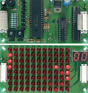
Pocket Pong
a primeval game cast in modern hardware

This is a MEMBER ONLY article. You need a subscription to read this article.
- Unlimited access to online Member Only articles
- 3 new editions Elektor Magazine (digital)
- More than 5000 Gerber files
- 20% member discount on e-books (at elektor.com)
- 10% member discount on Products (at elektor.com)
Available from €5.33 per month.
What is Members Only
Elektor is committed to providing high-quality content on electronics, catering to tens of thousands of paying members. As part of this commitment, Elektor has launched Premium, an initiative that offers exclusive online articles to members sometimes even before they appear in the magazine.
Every day, members can access in-depth articles that showcase the best of Elektor's premium content.
This initiative aims to reward members with early access. Once logged in, members can easily enjoy this exclusive content and engage in discussions about featured projects. While Premium adds to the existing resources available, Elektor will continue to provide a wealth of free information.
Join the Elektor community today to take advantage of Premium and other benefits!
Materials
Gerber file
CAM/CAD data for the PCB referred to in this article is available as a Gerber file. Elektor GREEN and GOLD members can exclusively download these files for free as part of their membership. Gerber files allow a PCB to be produced on an appropriate device available locally, or through an online PCB manufacturing service.
Elektor recommends the Elektor PCB Service service from its business partner Eurocircuits or AISLER as the best services for its own prototypes and volume production.
The use of our Gerber files is provided under a modified Creative Commons license. Creative Commons offers authors, scientists, educators and other creatives the freedom to handle their copyright in a more free way without losing their ownership.
Component list
R1,R2 = 1kOhm
R3-R6 = 10kOhm
R7 = 10Ohm
R8-R15 = 56Ohm
P1,P2 = 100kOhm preset
Capacitors:
C1,C2 = 100nF
C3,C4 = 22pF
C5 = 100µ F 10V radial
C6,C7,C8 = 100nF
C9 = 10µ F 63V radial
C10 = 470µ F 25V radial
Semiconductors:
D1-D88 = LED, red, high-efficiency, 5mm, e.g., HP HLMP-D101 (Farnell # 323-044)
D89 = 1N4001
LD1,LD2 = LTS4301E LiteOn
T1-T9 = BC547B
IC1 = PIC18F452-I/P
IC2 = 74HC4514 (74HCT4514 or 4514)
IC3,IC4 = ULN2803
IC5 = 4805
Miscellaneous:
K1 = P3 = 4kOhm 7 (5kOhm ) linear potentiometer, and a 3-way SIL pinheader
K2 = P4 = 4k7 linear potentiometer, mono, + 3-way SIL pinheader
K3,K4 = 16-way boxheader
K5,K6 = 16-way flatcable connector for PCB mounting
S1 = pushbutton, 1 make contact
S2 = not fitted
S3 = switch, on/off
X1 = 4MHz quartz crystal
BZ1 = 5V (DC) piezo buzzer


Discussion (0 comments)