

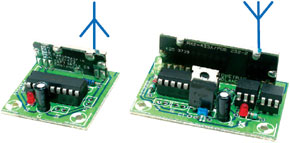
Canon EOS Cameras go Wireless
Using 433-MHz SRD modules
This is a MEMBER ONLY article. You need a subscription to read this article.
- Access to Elektor archive and 5,000+ Gerber files
- Receive up to 8 magazines per year (digital and/or paper)
- 10% discount in the Elektor store
Available from €4.95 per month.
What is Members Only
Elektor is committed to providing high-quality content on electronics, catering to tens of thousands of paying members. As part of this commitment, Elektor has launched Premium, an initiative that offers exclusive online articles to members sometimes even before they appear in the magazine.
Every day, members can access in-depth articles that showcase the best of Elektor's premium content.
This initiative aims to reward members with early access. Once logged in, members can easily enjoy this exclusive content and engage in discussions about featured projects. While Premium adds to the existing resources available, Elektor will continue to provide a wealth of free information.
Join the Elektor community today to take advantage of Premium and other benefits!
Materials
Gerber file
CAM/CAD data for the PCB referred to in this article is available as a Gerber file. Elektor GREEN and GOLD members can exclusively download these files for free as part of their membership. Gerber files allow a PCB to be produced on an appropriate device available locally, or through an online PCB manufacturing service.
Elektor recommends the Elektor PCB Service service from its business partner Eurocircuits or AISLER as the best services for its own prototypes and volume production.
The use of our Gerber files is provided under a modified Creative Commons license. Creative Commons offers authors, scientists, educators and other creatives the freedom to handle their copyright in a more free way without losing their ownership.
Extra info / Update
In the transmitter circuit diagram, pushbutton S1 should be a normally closed (NC) type.
Component list
Resistors:
R1 = 10kOhm
R2 = 470Ohm
R3 = 976kOhm 1%
Capacitors:
C1 = 10µF 25V radial
Semiconductors:
D1 = 1N4148
D2 = LED, red
IC1 = HT12E (Holtek) (Maplin Electronics)
Miscellaneous:
ANT1 = stiff wire, length approx. 15.5cm
BT1 = 9V battery connection
MOD1 = TX2 433MHz SRD radio module (Radiometrix). Equivalents from LPRS (www.lprs.co.uk)
S1 = pushbutton, 1 make contact (see also inset)
S2 = on/off switch
Receiver
Resistors:
R1 = 51kOhm1 1%
R2,R3 = 220Ohm
R4,R5 = 150Ohm
Capacitors:
C1 = 100nF
C2 = 10µF 25V radial
Semiconductors:
D1 = LED, green
D2 = LED, red
IC1 = HT12D (Holtek) (Maplin Electronics)
IC2 = 7805
IC3,IC4 = CNY17-2
Miscellaneous:
ANT1 = stiff wire, length approx. 15.5cm
BT1 = 9V battery connection
K1 = mini jack plug (2.5mm) with 3-wire cable
MOD1 = RX2 433MHz SRD receiver module (Radiometrix) ). Equivalents from LPRS (www.lprs.co.uk)
S1 = on/off switch
Discussion (0 comments)