

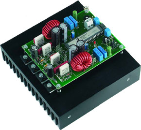
ClariTy 2x300W Class-T Amplifier, Part 2
building the amplifier board
This is a MEMBER ONLY article. You need a subscription to read this article.
- Unlimited access to online Member Only articles
- 3 new editions Elektor Magazine (digital)
- More than 5000 Gerber files
- 20% member discount on e-books (at elektor.com)
- 10% member discount on Products (at elektor.com)
Available from €5.33 per month.
What is Members Only
Elektor is committed to providing high-quality content on electronics, catering to tens of thousands of paying members. As part of this commitment, Elektor has launched Premium, an initiative that offers exclusive online articles to members sometimes even before they appear in the magazine.
Every day, members can access in-depth articles that showcase the best of Elektor's premium content.
This initiative aims to reward members with early access. Once logged in, members can easily enjoy this exclusive content and engage in discussions about featured projects. While Premium adds to the existing resources available, Elektor will continue to provide a wealth of free information.
Join the Elektor community today to take advantage of Premium and other benefits!
Materials
Gerber file
CAM/CAD data for the PCB referred to in this article is available as a Gerber file. Elektor GREEN and GOLD members can exclusively download these files for free as part of their membership. Gerber files allow a PCB to be produced on an appropriate device available locally, or through an online PCB manufacturing service.
Elektor recommends the Elektor PCB Service service from its business partner Eurocircuits or AISLER as the best services for its own prototypes and volume production.
The use of our Gerber files is provided under a modified Creative Commons license. Creative Commons offers authors, scientists, educators and other creatives the freedom to handle their copyright in a more free way without losing their ownership.
Component list
Resistors:
R6,R11,R27,R32 = 0Ohm 01, lead pitch 9mm, MPC75-E01 (H.O.D1 , Bürklin2)
R7,R9,R28,R30 = 5Ohm 6/1 W lead pitch 15mm (max.), PR01 BCComponents (Farnell # 337-584, 10+)
R12,R33 = 15Ohm 1W, PR01, BCComponents (Farnell # 337-638, 10+)
R13,R34 = 240Ohm
R14,R35 = 22Ohm 5W (vertical))
P1,P2 = 10kOhm preset
Capacitors:
C1,C14 = 3µ F3 50V, MKT, lead pitch 5mm or 7.5 mm
C4,C17 = 220pF 200 V, COG, lead pitch 5 mm, dipped radial multilayer ceramic, Multicomp (Farnell # 747-075, 1+)
C5,C18,C32,C33,C36,C37 = 100nF 250V, lead pitch 7.5mm or 10mm, w x l = 6 x 13 mm (max.), Wima MKS4 (Farnell # 148-888, 1+)
C6,C19 = 47µ F 160V radial, lead pitch 5mm, diameter 10mm (max.), 105ºC, Panasonic EEUED2C470 (Farnell # 83-6400, 1+)
C8,C21,C38 = 47µ F 25V radial
C9,C22 = 220nF 400V MKP, lead pitch 15mm, w x l = 8.5 x 18 mm (max.), Epcos B32652-A4224-J (Farnell # 400-3755, 1+)
C10,C23 = 100nF 400V MKP, lead pitch 15mm, w x l = 7 x 18 mm (max.), Epcos B32652-A4104-J (Farnell # 400-3731, 1+)
C30,C31,C34,C35 = 470µ F 63V radial, lead pitch 5mm, diameter 13 mm (max.), 105ºC, Nichicon UPM1J471MHH (Farnell # 415-3030, 5+)
Inductors:
L1,L2 = 11µ H3, 29 turns 1.5 mm ECW (SWG 16) on T106-2 core (Micrometals) (core supplied with pre-fitted PCB)
Semiconductors:
D1-D4,D8-D11 = MUR120 1 A/200 V ultra fast, ON Semiconductor (Farnell # 930-994, 1+)
D15 = LED, red, high efficiency
T1-T4 = STW38NB20, TO-247 case, 200 V/38 A, ST (Farnell # 323-9408, 1+)
IC1 = TA3020, Tripath3
IC2 = CNY17-2
Miscellaneous:
JP1,JP2 = 3-way pinheader with jumper
K1-K4,K6-K9 = spade terminal, vertical, PCB mount
K5 = 2-way PCB terminal block, lead pitch 5 mm
K10 = 2-way pinheader
48-pin IC socket, DIP socket with turned pins
Discussion (0 comments)