Article
Vehicle Battery Jogger
keep your battery fresh and young
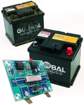
This design is a follow-up to the triumphant ‘Battery Revitaliser’ project published in the September 2001 issue of Elector Electronics. From numerous reader responses, it appears that defective batteries are a common problem. Since prevention is naturally better than cure, here we present a circuit that can keep your battery in shape in a simple but effective manner.The quality of lead-acid storage batteries has always been an awkward subject. Motorcyclists among our readers will be the first to agree with this. The most common example is a motorcycle that’s put in storage for the winter and proves to have battery problems when spring comes. This involves more than just the fact that the battery has become partially discharged, since in many cases the battery has also noticeably deteriorated. That can be seen from the fact that even immediately after being charged, it performs poorly and quickly loses it charge.
Materials
Gerber file
CAM/CAD data for the PCB referred to in this article is available as a Gerber file. Elektor GREEN and GOLD members can exclusively download these files for free as part of their membership. Gerber files allow a PCB to be produced on an appropriate device available locally, or through an online PCB manufacturing service.
Elektor recommends the Elektor PCB Service service from its business partner Eurocircuits or AISLER as the best services for its own prototypes and volume production.
The use of our Gerber files is provided under a modified Creative Commons license. Creative Commons offers authors, scientists, educators and other creatives the freedom to handle their copyright in a more free way without losing their ownership.
PCB
Component list
Resistors:
R1 = 6MOhm 8
R2 = 3MOhm 3
R3 = 4kOhm 7
R4,R5 = 10kOhm
R6 = 2kOhm 2
R7 = 100kOhm
R8 = 0Ohm 15, 5W or 10W
R9 = 150Ohm
Capacitors:
C1,C6 = 10ยต F 25V, radial
C2,C5 = 10nF
C3 = 1nF
C4 = 4nF7
C7 = 100nF
Semiconductors:
D1 = LED, low current
D2 = 1N4148
D3 = zener diode, 13V 0.5W
D4 = Schottky diode, e.g., BAT43, BAT85
D5 = fast zener diode, e.g., BZT03 24V, 27V or 33V)
T1 = BUZ10, BUZ11, BUZ100 or IRF540
IC1,IC2 = 7555 (CMOS)
PCB, ready-made, order code 044021-1
Discussion (0 comments)