

I²C-homebus
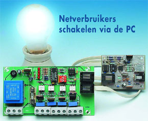
Switch power outlets with your PC
This is a MEMBER ONLY article. You need a subscription to read this article.
- Access to Elektor archive and 5,000+ Gerber files
- Receive up to 8 magazines per year (digital and/or paper)
- 10% discount in the Elektor store
Available from €4.95 per month.
What is Members Only
Elektor is committed to providing high-quality content on electronics, catering to tens of thousands of paying members. As part of this commitment, Elektor has launched Premium, an initiative that offers exclusive online articles to members sometimes even before they appear in the magazine.
Every day, members can access in-depth articles that showcase the best of Elektor's premium content.
This initiative aims to reward members with early access. Once logged in, members can easily enjoy this exclusive content and engage in discussions about featured projects. While Premium adds to the existing resources available, Elektor will continue to provide a wealth of free information.
Join the Elektor community today to take advantage of Premium and other benefits!
Materials
Gerber file
CAM/CAD data for the PCB referred to in this article is available as a Gerber file. Elektor GREEN and GOLD members can exclusively download these files for free as part of their membership. Gerber files allow a PCB to be produced on an appropriate device available locally, or through an online PCB manufacturing service.
Elektor recommends the Elektor PCB Service service from its business partner Eurocircuits or AISLER as the best services for its own prototypes and volume production.
The use of our Gerber files is provided under a modified Creative Commons license. Creative Commons offers authors, scientists, educators and other creatives the freedom to handle their copyright in a more free way without losing their ownership.
Component list
R1 = 47Ohm
R2 = 10kOhm 4-way SIL array
R3,R4 = 5kOhm6
R5-R8 = 270Ohm
R9-R12 = 1kOhm
R13,R16,R19,R22 = 390Ohm
R14,R17,R20,R23 = 330Ohm
R15,R18,R21,R24 = 39Ohm
R25,R26 = 10kOhm
Capacitors:
C1,C2,C3,C5,C6 = 100nF
C4 = 100µ F 16V radial
C7 = 10µ F 16V radial
C8-C11 = 10nF, safety class X2
Semiconductors:
B1 = B80C1500 in round case (80V piv, 1.5A)
D1 = LED, green, low current
D2-D5 = LED, red, low current
IC1 = P82B715PN (Farnell # 559-258)
IC2,IC5,IC6,IC7 = MOC3043 (Farnell # 885-710)
IC3 = PCF8574 (Digikey # 296-13106-5-ND)
IC4 = 7805
Tr1 = mains transformer, PCB mount, sec. 2 x 6V/2 x 1.5 VA (Farnell # 926-280)
Tri2-Tri5 = TIC206D (Conrad Electronics # 186333)
Miscellaneous:
F1 = fuse, 20mAT (time lag), with PCB mount holder
K3-K7 = 2-way PCB terminal block, lead pitch 7.5mm
K1,K2 = 6-way RJ11 connector (Farnell # 393-8359)
S1 = 3-way DIP switch
RJ11 cable (Farnell # 754-948)
PCB, order code 040333-1 (see Readers Service page or website)
Disk; all project software, order code 040333-11 or Free Download
Discussion (0 comments)