Article
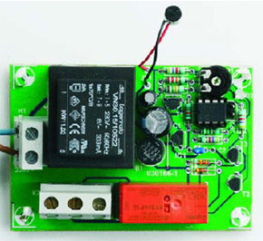
Intelligent Clap Switch
Manuel remote control with extras

A clap switch circuit is a classic beginner’s project. Equipment can
be switched on and off by just clapping your hands. Add a tiny microcontroller and you can easily build-in some more useful features.
The microcontroller in this circuit makes it a simple job to add some useful
features that are not seen on other clap switch designs:
– Changeover relay contacts enable the unit to be wired in conjunction
with a manual changeover switch so that manual override of the switched
equipment is always possible.
– The unit is only responsive to a specific sequence of sounds i.e., two
claps within a defined time window.
– A safety feature masks the input for a given time window if misuse
(repeated commands) is detected (useful if children have discovered how it works).
Materials
Gerber file
CAM/CAD data for the PCB referred to in this article is available as a Gerber file. Elektor GREEN and GOLD members can exclusively download these files for free as part of their membership. Gerber files allow a PCB to be produced on an appropriate device available locally, or through an online PCB manufacturing service.
Elektor recommends the Elektor PCB Service service from its business partner Eurocircuits or AISLER as the best services for its own prototypes and volume production.
The use of our Gerber files is provided under a modified Creative Commons license. Creative Commons offers authors, scientists, educators and other creatives the freedom to handle their copyright in a more free way without losing their ownership.
PCB
Component list
Resistors:
R1,R6,R7 = 4kOhm7
R2 = 150kOhm
R3 = 22kOhm
R4 = 10kOhm
R5 = 150Ohm
P1 = 100kOhm preset H
Capacitors:
C1 = 220µ F 25V radial
C2 = 100nF
C3 = 1µF 16V
Semiconductors:
B1 = B80C1500 (round case, 80V piv, 1.5A)
D1,D2 = 1N4148
D3 = bicolour LED (red/green)
IC1 = 78L05
IC2 = PIC12F629CP, programmed, order code 030166-41
T1,T2,T3 = BC238 or BC547
Miscellaneous:
JP1 = 2-way pinheader with jumper
K1 = 2-way PCB terminal block, lead pitch 7.5mm
K2 = 3- way PCB terminal block, lead pitch 7.5mm
MIC1 = 2-terminal electret microphone capsule
Re1 = bistable relay, 2 x changeover (e.g., Schrack RT314F12)
Tr1 = mains transformer 1 x 6V, min. 2VA, short-circuit proof (e.g., Marschner VN30.15/10522 or Era 030-7340.0T; Conrad Electronics # 506141)
PCB, order code 030166-1


Discussion (0 comments)