Playful Lights
Just three LEDs...

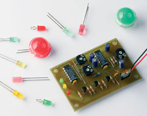
Here’s a recipe to make LEDs produce slow, continuous light effects rather than abrupt changes normally obtained from square-wave drive signals.
If you are after really accurate control of one or more LEDs, the best option by far is pulsewidth modulation (PWM) which is usually obtained from a dedicated PWM chip or a suitably programmed microcontroller. On the other hand, if the blink frequency not terriblyimportant, other, much simpler methods are available. For example, get out two square-wave oscillators running at slightly different frequencies and mix their outputs together in an XOR exclusive-OR) logic gate. That’s all it takes to build a beat-frequency oscillator whose low-frequency output signal may be pulse-width modulated in
triangular(-ish) fashion.
This is a MEMBER ONLY article. You need a subscription to read this article.
- Unlimited access to online Member Only articles
- 3 new editions Elektor Magazine (digital)
- More than 5000 Gerber files
- 20% member discount on e-books (at elektor.com)
- 10% member discount on Products (at elektor.com)
Available from €5.33 per month.
What is Members Only
Elektor is committed to providing high-quality content on electronics, catering to tens of thousands of paying members. As part of this commitment, Elektor has launched Premium, an initiative that offers exclusive online articles to members sometimes even before they appear in the magazine.
Every day, members can access in-depth articles that showcase the best of Elektor's premium content.
This initiative aims to reward members with early access. Once logged in, members can easily enjoy this exclusive content and engage in discussions about featured projects. While Premium adds to the existing resources available, Elektor will continue to provide a wealth of free information.
Join the Elektor community today to take advantage of Premium and other benefits!
Materials
Gerber file
CAM/CAD data for the PCB referred to in this article is available as a Gerber file. Elektor GREEN and GOLD members can exclusively download these files for free as part of their membership. Gerber files allow a PCB to be produced on an appropriate device available locally, or through an online PCB manufacturing service.
Elektor recommends the Elektor PCB Service service from its business partner Eurocircuits or AISLER as the best services for its own prototypes and volume production.
The use of our Gerber files is provided under a modified Creative Commons license. Creative Commons offers authors, scientists, educators and other creatives the freedom to handle their copyright in a more free way without losing their ownership.
Component list
R1,R8,R9,R10 = 1kO
R5,R6,R7 = 2k2
R2,R3,R4 = 976 1%
P1,P2,P3 = 50 preset
Capacitors:
C1-C4 = 22µF 16V radial
C5-C8 = 100nF
Semiconductors:
D1 = LED, green, low current
D2 = LED, yellow, low current
D3 = LED, red, low current
or:
D1,D2,D3 = RGB LED (e.g., Conrad Electronics # 185388 - 8B)
D4 = 1N4148
T1,T2,T3 = BC547
IC1 = 74HCT132
IC2 = 74HCT86
IC3 = 7805
Miscellaneous:
K1 = 9-V PP3 battery with clip-on leads


Discussion (0 comments)