

Toslink Repeater/Splitter
-
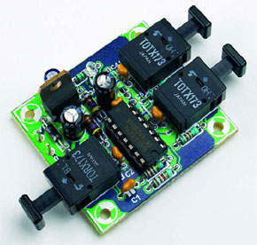
The circuit consists of the standard application for the Toslink receiver module TORX173 (IC1) and the Toslink transmitter module TOTX173 (IC2 and IC3), that we have used on previous occasions.
This is a MEMBER ONLY article. You need a subscription to read this article.
- Access to Elektor archive and 5,000+ Gerber files
- Receive up to 8 magazines per year (digital and/or paper)
- 10% discount in the Elektor store
Available from €4.95 per month.
What is Members Only
Elektor is committed to providing high-quality content on electronics, catering to tens of thousands of paying members. As part of this commitment, Elektor has launched Premium, an initiative that offers exclusive online articles to members sometimes even before they appear in the magazine.
Every day, members can access in-depth articles that showcase the best of Elektor's premium content.
This initiative aims to reward members with early access. Once logged in, members can easily enjoy this exclusive content and engage in discussions about featured projects. While Premium adds to the existing resources available, Elektor will continue to provide a wealth of free information.
Join the Elektor community today to take advantage of Premium and other benefits!
Materials
Gerber file
CAM/CAD data for the PCB referred to in this article is available as a Gerber file. Elektor GREEN and GOLD members can exclusively download these files for free as part of their membership. Gerber files allow a PCB to be produced on an appropriate device available locally, or through an online PCB manufacturing service.
Elektor recommends the Elektor PCB Service service from its business partner Eurocircuits or AISLER as the best services for its own prototypes and volume production.
The use of our Gerber files is provided under a modified Creative Commons license. Creative Commons offers authors, scientists, educators and other creatives the freedom to handle their copyright in a more free way without losing their ownership.
Component list
R1,R2 = 2k2
R3,R5 = 4,7
R4,R6 = 8k2
R7 = 1k5
Capacitors:
C1-C5 = 100nF
C6,C8 = 47µF 25V radial
C7 = 4µF7 63V radial
Inductors:
L1,L2 = 47µH
Semiconductors:
D1 = low-current LED, red
D2 = 1N4002
IC1 = TORX173
IC2,IC3 = TOTX173
IC4 = 74HCU04
IC5 = 7805
PCB, ref. 054005-1
Discussion (0 comments)