

Universal I/O for Power Amps
-
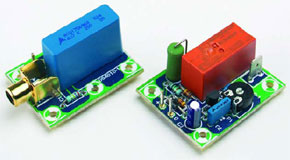
The circuit consists of an input stage (nothing more than a resistor and capacitor) and a power-on delay with a relay for the amplifier output.
A small PCB has been designed for the input signal. This board contains a phono socket, capacitor and a resistor that is connected directly across the input.
This is a MEMBER ONLY article. You need a subscription to read this article.
- Unlimited access to online Member Only articles
- 3 new editions Elektor Magazine (digital)
- More than 5000 Gerber files
- 20% member discount on e-books (at elektor.com)
- 10% member discount on Products (at elektor.com)
Available from €5.33 per month.
What is Members Only
Elektor is committed to providing high-quality content on electronics, catering to tens of thousands of paying members. As part of this commitment, Elektor has launched Premium, an initiative that offers exclusive online articles to members sometimes even before they appear in the magazine.
Every day, members can access in-depth articles that showcase the best of Elektor's premium content.
This initiative aims to reward members with early access. Once logged in, members can easily enjoy this exclusive content and engage in discussions about featured projects. While Premium adds to the existing resources available, Elektor will continue to provide a wealth of free information.
Join the Elektor community today to take advantage of Premium and other benefits!
Materials
Gerber file
CAM/CAD data for the PCB referred to in this article is available as a Gerber file. Elektor GREEN and GOLD members can exclusively download these files for free as part of their membership. Gerber files allow a PCB to be produced on an appropriate device available locally, or through an online PCB manufacturing service.
Elektor recommends the Elektor PCB Service service from its business partner Eurocircuits or AISLER as the best services for its own prototypes and volume production.
The use of our Gerber files is provided under a modified Creative Commons license. Creative Commons offers authors, scientists, educators and other creatives the freedom to handle their copyright in a more free way without losing their ownership.
Component list
R1 = 270k
R2 = 1k2
R3,R4 = 1M
P1 = 250k preset
Capacitors:
C1 = 4µF7 MKT or MKP (see text)
C2 = 47nF
C3 = 10µF 63V radial
Semiconductors:
D1,D3 = 1N4148
D2 = zener diode 24V 1.3W
D4 = 1N4002
T1 = BS170
Miscellaneous:
K1 = cinch socket, PCB mount, e.g. Monacor / Monarch T-709G
K2, K3 = spade terminal, PCB mount, vertical, 2 pins
RE1 = PCB relay 24 V/16 A (e.g., Omron G2R-1-24, 1100 Ohm, or Schrack RT314024, 1440 Ohm)
PCB, ref. 054010-1
Discussion (0 comments)