

PIC PWM Controller
-
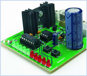
A little 8-pin microcontroller can do these tasks easily: generating a PWM signal and indicating the power via a 4017.
This is a MEMBER ONLY article. You need a subscription to read this article.
- Unlimited access to online Member Only articles
- 3 new editions Elektor Magazine (digital)
- More than 5000 Gerber files
- 20% member discount on e-books (at elektor.com)
- 10% member discount on Products (at elektor.com)
Available from €5.33 per month.
What is Members Only
Elektor is committed to providing high-quality content on electronics, catering to tens of thousands of paying members. As part of this commitment, Elektor has launched Premium, an initiative that offers exclusive online articles to members sometimes even before they appear in the magazine.
Every day, members can access in-depth articles that showcase the best of Elektor's premium content.
This initiative aims to reward members with early access. Once logged in, members can easily enjoy this exclusive content and engage in discussions about featured projects. While Premium adds to the existing resources available, Elektor will continue to provide a wealth of free information.
Join the Elektor community today to take advantage of Premium and other benefits!
Materials
Gerber file
CAM/CAD data for the PCB referred to in this article is available as a Gerber file. Elektor GREEN and GOLD members can exclusively download these files for free as part of their membership. Gerber files allow a PCB to be produced on an appropriate device available locally, or through an online PCB manufacturing service.
Elektor recommends the Elektor PCB Service service from its business partner Eurocircuits or AISLER as the best services for its own prototypes and volume production.
The use of our Gerber files is provided under a modified Creative Commons license. Creative Commons offers authors, scientists, educators and other creatives the freedom to handle their copyright in a more free way without losing their ownership.
Component list
R1 = 100k
R2,R3 = 4k7
R4 = 220
Capacitors:
C1 = 2200µF 25V
C2 = 10µF 25V
C3-C6 = 100nF
Semiconductors:
D1 = 1N5408
D2 = 1N4148
D3-D7 = LED, 3mm, green
D8-D12 = LED, 3mm, red
T1 = IRFZ34N
T2 = BS170
IC1 = 78L05
IC2 = PIC 12C508-I/P
IC3 = CD 4017
Miscellaneous:
K1,K2 = 2-way PCB terminal block, lead pitch 5mm
S1,S2 = pushbutton, 1 make contact, DTS6
F1 = 2 AT (time lag) fuse with PCB mount holder
Heatsink type SK104 (Fischer)
PCB, ref. 050056-1
PIC source and hex code, ref. 050056-11
Discussion (0 comments)