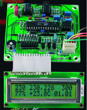
Hitting the High Notes
An ultrasonic distance meter & liquid-level gauge

This is a MEMBER ONLY article. You need a subscription to read this article.
- Unlimited access to online Member Only articles
- 3 new editions Elektor Magazine (digital)
- More than 5000 Gerber files
- 20% member discount on e-books (at elektor.com)
- 10% member discount on Products (at elektor.com)
Available from €5.33 per month.
What is Members Only
Elektor is committed to providing high-quality content on electronics, catering to tens of thousands of paying members. As part of this commitment, Elektor has launched Premium, an initiative that offers exclusive online articles to members sometimes even before they appear in the magazine.
Every day, members can access in-depth articles that showcase the best of Elektor's premium content.
This initiative aims to reward members with early access. Once logged in, members can easily enjoy this exclusive content and engage in discussions about featured projects. While Premium adds to the existing resources available, Elektor will continue to provide a wealth of free information.
Join the Elektor community today to take advantage of Premium and other benefits!
Materials
Gerber file
CAM/CAD data for the PCB referred to in this article is available as a Gerber file. Elektor GREEN and GOLD members can exclusively download these files for free as part of their membership. Gerber files allow a PCB to be produced on an appropriate device available locally, or through an online PCB manufacturing service.
Elektor recommends the Elektor PCB Service service from its business partner Eurocircuits or AISLER as the best services for its own prototypes and volume production.
The use of our Gerber files is provided under a modified Creative Commons license. Creative Commons offers authors, scientists, educators and other creatives the freedom to handle their copyright in a more free way without losing their ownership.
Component list
Resistor:
R1 = 33k
Capacitors*:
C1,C2,C6,C8,C9 = 220µF 25V radial
C3,C5,C7,C10 = 100µF 25V radial
C4 = 470µF 16V radial
C11 = 10nF
Semiconductors:
B1 = bridge rectifier 80V (or 40V), 0.8 A
D1-D4 = 1N4001
IC1 = 7815
IC2 = 7805
IC3 = 7905
IC4 = 7915
Miscellaneous:
K1 = 5-way SIL header
K2 = 2-way PCB terminal block, lead pitch 7.5mm
Tr1 = mains transformer 2 x 6V @ 2 x 233mA (e.g., ERA BV030-7590.0U)
F1 = fuse, 63mAT (time lag), with PCB mount holder (lead pitch 22.5mm) (not required if a short-circuit resistant transformer is used)
Main circuit board
Resistors:
R1,R3 = 3k
R2 = 68k
R4 = 110k
R5 = 16k
R6 = 3k3
R7 = 56k
R8 = 10k
R9 = 270, 1%
R10 = 750, 1%
R11 = 33
R12 = 22k
R13,R16,R18 = 120k
R14,R17 = 180k
R15,R19,R20 = 82k
R21 = 47k
R22 = 1k5
R23,R24,R25 = 5k6
R26-R33 = 270
P1 = 10k preset, H
Capacitors*:
C1,C3 = 2nF2
C2 = 27pF
C4 = 15pF
C5 = 1µF, lead pitch 5mm or 7.5mm
C6 = 33nF
C7 = 10nF
C8,C11,C12,C14, C15,C16,C17 = 100nF
C9,C10 = 22pF
C13 = 220nF, lead pitch 5mm or 7.5mm
Semiconductors:
D1 = 1N4148
T1,T2,T3 = BC557A
IC1,IC4 = TL082P
IC2 = ATmega8-16PC, programmed, order code 040015-41
IC3 = LM833N
Miscellaneous:
X1 = 8MHz quartz crystal
K1 = 5-way pinheader and mating socket
K2 = 6-way pinheader (2x3 block)
K3 = 3-way pinheader, straight
K4 = 16-way pinheader, straight
K5 = 14-way (2x7) pinheader, straight
K6 = 9-way D subminiature socket (female)
Solder pins
1 off 28-way IC socket, narrow-DIL
3 off 8-way IC socket
S1 = pushbutton, 1 make contact
LCD module with 44780 controller; 2x16 characters (optionally: with backlight; Display Tech 162)
ABS case, min. inside dimensions 125 x 102mm (splashproof; approved for damp room / outdoor use)
Display board
LD1,LD2,LD3 = 7-segment display, common anode, 20mm high (Kingbright SA08-11 SRWA)
K1 = 14-way (2x7) pinheader
Sensor head
R1 = NTC, 10k
R2 = 12k, 1%
UT1 = ultrasonic emitter (36-40 kHz)
UR1 = ultrasonic receiver (36-40 kHz)
5-way cable with individual screening (e.g., microphone cable); see text
Splashproof ABS case with strain relief grommet and locking nut (Bopla ET205, BF7, GM7)
*All capacitors 5mm lead pitch unless otherwise indicated
Ultrasonic transmitter and receiver
Suggested sources and order numbers:
maplin
HY12N (receiver/transmitter pair)
conrad
400ST160/MA40-S182273-12
400ST160/MA40-R182281-12
reichelt
400ST160/UST-40TUST-40T
400SR160/UST-40RUST-40R
segor
UST-40 TUST-40 T
UST-40 RUST-40 R
simons-elektronik
UST-40TUST-40T
UST-40RUST-40R


Discussion (0 comments)