Article
Synchronous Servos
Tracking control with ServoMagic
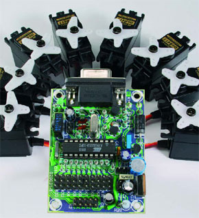
Model servos are frequently used in robotics projects because of their unique properties. However, a significant disadvantage is that servos often change position far too quickly. In addition, each servo moves at a slightly different speed, which results in erratic looking movements. In these situations it would be nice if all connected servos would move simultaneously and with a user-defined speed to the next position. This synchronous servo control (called ServoMagic) is the solution for this problem.
Materials
Gerber file
CAM/CAD data for the PCB referred to in this article is available as a Gerber file. Elektor GREEN and GOLD members can exclusively download these files for free as part of their membership. Gerber files allow a PCB to be produced on an appropriate device available locally, or through an online PCB manufacturing service.
Elektor recommends the Elektor PCB Service service from its business partner Eurocircuits or AISLER as the best services for its own prototypes and volume production.
The use of our Gerber files is provided under a modified Creative Commons license. Creative Commons offers authors, scientists, educators and other creatives the freedom to handle their copyright in a more free way without losing their ownership.
PCB
Component list
Resistors:
R1 = 100?
R2 = 330?
R3 = 10k?
R4, R10-R19 = 1k?
R5 = 100 k?
R6, R7 = 4k?7
R8, R21 = 47k?
R9 = 470?
R20 = 1? 1W
Capacitors:
C1 = 4?F7 10V radial
C2, C3 = 27pF
C4 = 220nF
C5 = 10?F 16V radial
C6, C7, C9 = 100?F 25V radial
C8, C10, C11 = 100nF
Semiconductors:
D1 = 1N4148
D2 = LED, 3mm, green
D3 = 1N5401
IC1 = IR receiver (see text)
IC2 = AT90S2313-10PC, programmed for RS232, order code 020031-41)
IC3 = 78S05
IC4 = 78L05
T1,T2 = BC547B
Miscellaneous:
JP1 = jumper
K1 = 9-way sub-D socket (female), angled pins, PCB mount
K2 = 10-way pinheader
K3 = connection for IR receiver
K4-K13 = 3-way pinheader
S1,S2 = pushbutton, 1 make contact
X1 = 4MHz quartz crystal
Heatsink for IC3, e.g., FK237, ICK35
2 wire links
RS232 cable, straight-through (all wires 1:1 connected)
PCB, no. 020031-1 from The PCBShop
project software, code 020031-11
Discussion (0 comments)