

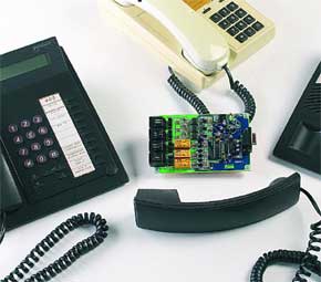
Telephone Supervisor
Oops, Big Brother on the phone!
This is a MEMBER ONLY article. You need a subscription to read this article.
- Access to Elektor archive and 5,000+ Gerber files
- Receive up to 8 magazines per year (digital and/or paper)
- 10% discount in the Elektor store
Available from €4.95 per month.
What is Members Only
Elektor is committed to providing high-quality content on electronics, catering to tens of thousands of paying members. As part of this commitment, Elektor has launched Premium, an initiative that offers exclusive online articles to members sometimes even before they appear in the magazine.
Every day, members can access in-depth articles that showcase the best of Elektor's premium content.
This initiative aims to reward members with early access. Once logged in, members can easily enjoy this exclusive content and engage in discussions about featured projects. While Premium adds to the existing resources available, Elektor will continue to provide a wealth of free information.
Join the Elektor community today to take advantage of Premium and other benefits!
Materials
Gerber file
CAM/CAD data for the PCB referred to in this article is available as a Gerber file. Elektor GREEN and GOLD members can exclusively download these files for free as part of their membership. Gerber files allow a PCB to be produced on an appropriate device available locally, or through an online PCB manufacturing service.
Elektor recommends the Elektor PCB Service service from its business partner Eurocircuits or AISLER as the best services for its own prototypes and volume production.
The use of our Gerber files is provided under a modified Creative Commons license. Creative Commons offers authors, scientists, educators and other creatives the freedom to handle their copyright in a more free way without losing their ownership.
Component list
R1,R3,R5,R7,R9,R11 = 220
R2,R6,R10 = 1k
R4,R8,R12,R13 = 47k
R14 = 330
R15-R22 = 10k
R23,R24,R25 = 22k
R26 = 1k8
Capacitors:
C1,C11 = 100nF (C1 5mm lead pitch)
C2,C5 = 220µF 16V radial
C3 = 22nF, lead pitch 5mm
C4,C7-C10 = 4µF7 63V radial
C6 = 220µF 25V radial
Inductors:
L1 = 47µH
Semiconductors:
D1-D22 = 1N4148
D23 = LED, low current
D24 = 1N4007
T1-T3 = BC212B
T4 = BC549C or BC550C
T5-T10 = BC237B
IC1 = PIC16F628-20/P, programmed, order code 050039-41*
IC2 = MAX232
IC3,IC4,IC5 = IL250 (H11AA4)
IC6 = 78L05
IC7 = 7809
Miscellaneous:
JP1-JP16 = 2-way pinheader and 8 jumpers
K1-K4 = RJ11 PCB mount socket
K5 = 9-way sub-D socket (female), angled pins, PCB mount
X1 = not fitted, see text
RE1,RE2,RE3 = 12V PCB relay, bistable, two energising solenoids 2 x 400?, two changeover contacts, e.g., DS2E-ML2-12VJ Panasonic (Schuricht # 407220; www.schuricht.de)
2 wire links
LCM First Server 1.1 + PIC source & hex code files 050039-81
PCB, ref. 050039-1 from The PCBShop
Discussion (0 comments)