

Brushless Motor Controller
Speed control for radio controlled scale models
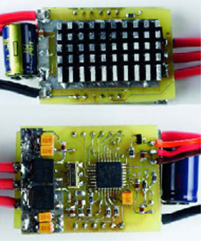
massive interest in recent years for this type of propulsion system has made it possible to take electric motors to record levels in terms of efficiency and compactness, with the inevitable trade-off of increased complexity in control electronics. This article describes the basic theoretical principles linked to the operation of these motors, and a solution that is dependent on the ST7 microcontroller, recently introduced to the market and completely dedicated to this type of application.
This is a MEMBER ONLY article. You need a subscription to read this article.
- Access to Elektor archive and 5,000+ Gerber files
- Receive up to 8 magazines per year (digital and/or paper)
- 10% discount in the Elektor store
Available from €4.95 per month.
What is Members Only
Elektor is committed to providing high-quality content on electronics, catering to tens of thousands of paying members. As part of this commitment, Elektor has launched Premium, an initiative that offers exclusive online articles to members sometimes even before they appear in the magazine.
Every day, members can access in-depth articles that showcase the best of Elektor's premium content.
This initiative aims to reward members with early access. Once logged in, members can easily enjoy this exclusive content and engage in discussions about featured projects. While Premium adds to the existing resources available, Elektor will continue to provide a wealth of free information.
Join the Elektor community today to take advantage of Premium and other benefits!
Materials
Gerber file
CAM/CAD data for the PCB referred to in this article is available as a Gerber file. Elektor GREEN and GOLD members can exclusively download these files for free as part of their membership. Gerber files allow a PCB to be produced on an appropriate device available locally, or through an online PCB manufacturing service.
Elektor recommends the Elektor PCB Service service from its business partner Eurocircuits or AISLER as the best services for its own prototypes and volume production.
The use of our Gerber files is provided under a modified Creative Commons license. Creative Commons offers authors, scientists, educators and other creatives the freedom to handle their copyright in a more free way without losing their ownership.
Component list
Resistors:
R1,R4 = not fitted
R2 = 4k7
R3,R5 = 10k
R6 = 22k
R7 = 15k
R8 = 5,6
R9 = 5k1
R10-R15 = 6k8
R16 = 3k3
Capacitors:
C1,C2,C3,C5,C6,C7 = 100nF
C4 = not fitted
C8 = 10nF
C9*,C12* = 4µF7 20V low-ESR
C10 = 47µF 6V3
C11* = 2µF2 5V low-ESR
Semiconductors:
D1 = BAT54
IC1 = M24C01
IC2 = ST7MC1, programmed, Publishers order code 050157-41)
IC3,IC4 = L4941 BA05FP
Miscellaneous:
X1 = 8MHz quartz crystal
K1,K2 = see text
K3 = 3-way SIL header with 1 jumper
PCB, ref, 050157-1 from The PCBShop
Power driver board (050157-1)
Resistors:
R25-R30 = 270
R31-R36 = 1k
R37-R48 = 240
Capacitors:
C1,C11-C17 = 100nF
C2-C10 = not fitted
C18 = 470µF 6V3
Semiconductors:
D1,D2,D3 = BAT54A
D4,D5,D6 = BAT54C
T16-T21 = FDS6675
T22-T27 = BSS138, 2N7002
T28-T33 = PHK12NQ03LT
T34-T39 = BC817-40
T40,T42,T43 = BC807-40
T41 = not fitted
Miscellaneous:
K2,K3 = see text.
PCB, ref. 050157-2 from The PCBShop.
Generic library, file # 050157-11, Free Download, February 2006.
User Manual, file # 050157-13, Free Download, February 2006.
Discussion (0 comments)