

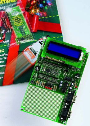
Application Board for R8C/13
Base camp for high Endeavour’s
This is a MEMBER ONLY article. You need a subscription to read this article.
- Unlimited access to online Member Only articles
- 3 new editions Elektor Magazine (digital)
- More than 5000 Gerber files
- 20% member discount on e-books (at elektor.com)
- 10% member discount on Products (at elektor.com)
Available from €5.33 per month.
What is Members Only
Elektor is committed to providing high-quality content on electronics, catering to tens of thousands of paying members. As part of this commitment, Elektor has launched Premium, an initiative that offers exclusive online articles to members sometimes even before they appear in the magazine.
Every day, members can access in-depth articles that showcase the best of Elektor's premium content.
This initiative aims to reward members with early access. Once logged in, members can easily enjoy this exclusive content and engage in discussions about featured projects. While Premium adds to the existing resources available, Elektor will continue to provide a wealth of free information.
Join the Elektor community today to take advantage of Premium and other benefits!
Materials
Gerber file
CAM/CAD data for the PCB referred to in this article is available as a Gerber file. Elektor GREEN and GOLD members can exclusively download these files for free as part of their membership. Gerber files allow a PCB to be produced on an appropriate device available locally, or through an online PCB manufacturing service.
Elektor recommends the Elektor PCB Service service from its business partner Eurocircuits or AISLER as the best services for its own prototypes and volume production.
The use of our Gerber files is provided under a modified Creative Commons license. Creative Commons offers authors, scientists, educators and other creatives the freedom to handle their copyright in a more free way without losing their ownership.
Component list
R1-R4,R7 = 1k
R5 = 1k5
R6 = 47k
R8,R9,R10 = 4k7
R11 = 33k
R12,R13,R14 = 220k
R15,R16 = 27
R17 = 10k
P1,P2 = 10k
Capacitors:
C1-C4,C8,C11,C12,C18 = 100nF
C5,C6 = 10pF
C7,C9,C13 = 10µF 16V radial
C10 = 220µF 25V
C14-C17 = 4µF7 25V radial
Semiconductors:
D1-D4,D6 = LED
D5 = 1N4002
D7 = 1N4148
IC1 = PL2303X (Prolific)
IC2 = 7805
IC3 = MAX232
Miscellaneous:
JP3-JP6,JP12 = jumper
JP7-JP11 = 3-way SIL pinheader
K1 = 2-way PCB terminal block, lead pitch 5mm
K2 = USB socket, type B for PCB mounting
K3,K4 = 9-way sub-D socket, angled pins, PCB mount
K5-K8 = 16-way SIL pinheader
K9 = LCD module, 2x16 characters
S1 = pushbutton with 1 make contact (e.g. TS695)
F1 = 100 mA Polyfuse
X2 = 12MHz quartz crystal
PCB, bare, order code 050179-1
PCB, ready-assembled and tested, order code 050179-92
LCD with backlight, order code 030451-72
Poly-LED display, order code 030451-73
Discussion (0 comments)