Article
Simple Rechargeable AA Cell Characteriser
The good, the bad and the flaky

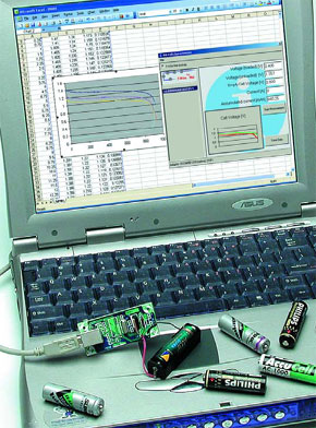
Rechargeable 1.2-V AA cells are very popular for a large variety of (portable) applications. The number of different brands is enormous and consequently the quality of these cells can differ considerably. Not surprisingly, the real capacity of cells is sometimes vastly different from what’s specified, and in quite a few cases the capacity deteriorates dramatically after just a couple of charge/discharge cycles. This circuit tells a harsh tale on flaky AA cells.
Materials
Gerber file
CAM/CAD data for the PCB referred to in this article is available as a Gerber file. Elektor GREEN and GOLD members can exclusively download these files for free as part of their membership. Gerber files allow a PCB to be produced on an appropriate device available locally, or through an online PCB manufacturing service.
Elektor recommends the Elektor PCB Service service from its business partner Eurocircuits or AISLER as the best services for its own prototypes and volume production.
The use of our Gerber files is provided under a modified Creative Commons license. Creative Commons offers authors, scientists, educators and other creatives the freedom to handle their copyright in a more free way without losing their ownership.
PCB
Extra info / Update
Please note: Murata recently changed the type code of inductors L1 and L2 from BLM21P221SG into BLM21PG221SN1J.
Resistor R3 is not shown in the circuit diagram. R3 is a 10-k pull-up resistor between the gate of T1 and the +5 V supply rail. It is present on the printed circuit board. R4 is a leaded component, not an SMD as suggested by the parts list.
Just after printing this article a problem occurred with the software supplied by the author. For this software to run, the user’s PC must have Microsoft Java installed. For various reasons Microsoft is no longer allowed to use the name ‘Java’ and the relevant program is no longer found on the Internet (but Google for MSJAVx86.exe and you will still be able to find it).
No problems are usually encountered on PCs running Windows 95 or 98 as MS-Java will be resident and the program AA-CELL msjava.ZIP may be run without problems.
The author has adapted his software to avoid the use of MS-Java. This requires changes to the installation. The following steps are recommended.
1. Install the 1-Wire divers including .NET support (note when to actually connect the circuit, this is indicated during the installation; start without the circuit connected to the USB).
http://files.dalsemi.com/auto_id/licensed/install_1_wire_drivers_v400.msi
2. Download Microsoft .NET Framework 2.0 redistributible package and install it (heft file at 23 Mbytes)
http://www.microsoft.com/downloads/details.aspx?familyid=0856EACB-4362-4B0D-8EDD-AAB15C5E04F5&displaylang=en
3. Download Microsoft Visual J# 2.0 Redistributable Package and install it.
http://www.microsoft.com/downloads/details.aspx?familyid=F72C74B3-ED0E-4AF8-AE63-2F0E42501BE1&displaylang=en
4. Download the project software (AA-CELL dotnet.zip) from the Elektor website and install it.
5. Start > Programs > 1-Wire Drivers > start Default 1-Wire Net and select the DS9490 (USB) adapter.
6. Start > Programs > Maxim Integrated Products > AAcellchar
That completes the modified installation procedure.
Component list
Resistors:
All SMD, case shape 0805
R1 = 1k5
R2 = 1k
R3 = 10k
R4 = 1Ohm, 2W
R5,R6 = 27Ohm
Capacitors:
All SMD, case shape 0805
C1 = 1µF
C2 = 4µF7
C3,C5 = 100nF
C4 = 10nF
C6-C9 = 33pF
Inductors:
L1,L2 = BLM21P221SN1J (Murata) (220Ohm @ 100MHz)
Semiconductors:
T1 = IRFZ24N
IC1 = MAX8881EUT33 (Maxim/Dallas)
IC2 = DS2490S (Maxim/Dallas)
IC3 = DS2751E-025 (Maxim/Dallas)
Miscellaneous:
K1 = USB connector, PCB mount, Type B
Battery holder for one AA cell (‘penlight’)\
PCB, order code 050394-1, see Readers Service page or SHOP on website
PC software, code 050394-11
All SMD, case shape 0805
R1 = 1k5
R2 = 1k
R3 = 10k
R4 = 1Ohm, 2W
R5,R6 = 27Ohm
Capacitors:
All SMD, case shape 0805
C1 = 1µF
C2 = 4µF7
C3,C5 = 100nF
C4 = 10nF
C6-C9 = 33pF
Inductors:
L1,L2 = BLM21P221SN1J (Murata) (220Ohm @ 100MHz)
Semiconductors:
T1 = IRFZ24N
IC1 = MAX8881EUT33 (Maxim/Dallas)
IC2 = DS2490S (Maxim/Dallas)
IC3 = DS2751E-025 (Maxim/Dallas)
Miscellaneous:
K1 = USB connector, PCB mount, Type B
Battery holder for one AA cell (‘penlight’)\
PCB, order code 050394-1, see Readers Service page or SHOP on website
PC software, code 050394-11


Discussion (0 comments)