Article
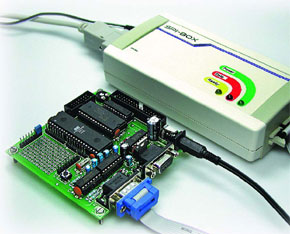
Universal SPI Box
A quicker way to program microcontrollers

Lots of microcontrollers can be programmed over an SPI bus. Driving this interface from a PC’s serial port using a couple of extra components is economical but slow. A better solution is the SPI Box described here, which gives acceptable speed even when used with a USB-to-serial converter.
Materials
Gerber file
CAM/CAD data for the PCB referred to in this article is available as a Gerber file. Elektor GREEN and GOLD members can exclusively download these files for free as part of their membership. Gerber files allow a PCB to be produced on an appropriate device available locally, or through an online PCB manufacturing service.
Elektor recommends the Elektor PCB Service service from its business partner Eurocircuits or AISLER as the best services for its own prototypes and volume production.
The use of our Gerber files is provided under a modified Creative Commons license. Creative Commons offers authors, scientists, educators and other creatives the freedom to handle their copyright in a more free way without losing their ownership.
PCB
Extra info / Update
Q: Hi did you realise that both the printed & downloadable PCB layouts for the SPI box project (April 2006) have no holes marked for the components ? Do you have a file which has the holes correctly shown which you could email me ?
A: Due to conversion problems experienced with the PCB files supplied by the author of the SPI Box project we have been unable to print PCB artwork with holes. As an alternative solution we are now offering Gerber files for the relevant board. The Gerber files are supplied free of charge and contain all PCB drilling information.
A: Due to conversion problems experienced with the PCB files supplied by the author of the SPI Box project we have been unable to print PCB artwork with holes. As an alternative solution we are now offering Gerber files for the relevant board. The Gerber files are supplied free of charge and contain all PCB drilling information.
Component list
R1,R5,R6,R7,R9,R12,R14 = 10k
R2 = 820
R3 = 1k8
R4 = 680
R8, R11 = 1M
R10 = 4k7
R13 = 470
R15 = 100
Capacitors
C1-C5,C10 = 10µF 35V radial
C6 = 1000µF 35 V axial
C7,C9 = 22pF
C8,C12-C17 = 100nF
C11 = 100µF 16V radial
C18 = 47pF
Semiconductors
D1 = 1N4001
D2 = LED, yellow, low current
D3 = LED, red, low current
D4 = LED, green, low current
D5,D6,D9,D10 = BAW76
D7 = 1N4148
D8 = zener diode 3V9, 400 mW
IC1 = MAX232ACPE
IC2 = 7805
IC3 = TL7705ACP
IC4 = 74LS06
IC5 = AT89C2051-24PC, programmed, order code 050198-41*
IC6 = 74HC14
T1 = BC558C
Miscellaneous
X1 = 22.1184MHz quartz crystal
Bu1, Bu2 = mains adaptor socket for 2.1 mm plug, angled, PCB mount
K1 = 9-way sub-D socket, angled, PCB mount
K2 = 10-way boxheader, angled pins
Sockets for IC4, IC5 and IC6
Heatsink for IC2 (TO-220 case)
Case, OKW type TOPTEC 154F
Mains adaptor with 2.1 mm plug (negative on outer ring), 8-15VDC @ 300mA
PCB, order code 050198-1 *
PC software, AT89S binary & hex files: Download no. 050198-11


Discussion (0 comments)