Article
DRM Receiver Upgrade
-

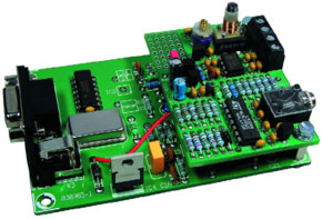
The DRM Receiver described in the March 2004 issue of Elektor Electronics has proved very popular and many thousand of the receivers are already in the field. Its excellent design is both simple and inexpensive. In the best tradition of homebrew construction we have supported the receiver by publishing two add-ons to the basic design; an automatic preselector (11/04) and an automatic gain control (2/06).
Materials
Gerber file
CAM/CAD data for the PCB referred to in this article is available as a Gerber file. Elektor GREEN and GOLD members can exclusively download these files for free as part of their membership. Gerber files allow a PCB to be produced on an appropriate device available locally, or through an online PCB manufacturing service.
Elektor recommends the Elektor PCB Service service from its business partner Eurocircuits or AISLER as the best services for its own prototypes and volume production.
The use of our Gerber files is provided under a modified Creative Commons license. Creative Commons offers authors, scientists, educators and other creatives the freedom to handle their copyright in a more free way without losing their ownership.
PCB
Component list
Resistors
R1,R4,R6,R14,R18,R20 = 1k
R2,R3,R8,R10-R13,R16,R17,R19 = 27k
R5 = 1M
R9 = 270k
R7 = 470
R15 = 100
Capacitors
C1,C3,C5-C14,C16,C19-C22 = 100nF
C2 = 100pF
C4 = 22pF
C15 = 10µF 16V radial
C17 = 45pF trimmer
C18 = 47µF 16V radial
Semiconductors
D1 = BB313 or 3 off BB112
D2 = 1N4001
T1 = BF245
T2,T3 = BS107, BS170
IC1 = NE612
IC2 = LM324
IC3 = 78L05
Miscellaneous
J1 = Jumper
CON1,CON2 = 2-way PCB terminal block, lead pitch 5mm
CON3 = 3.5mm jack socket
CON4,CON5 = pinheader or wires
CON6,CON7 = 1mm dia. solder pin
L1 = inductor former with core (Conrad Electronics # 516651) and ECW 0.3mm
L2 = 2µH2 fixed inductor
PCB, ref. 060140-1
Suggested kit supplier: www.geist-electronic.de
Ready built and tested units from: www.modul-bus.de


Discussion (0 comments)