

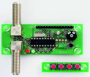
DiSEqC Monitor
PIC listens in on satellite receiver control bus
This is a MEMBER ONLY article. You need a subscription to read this article.
- Unlimited access to online Member Only articles
- 3 new editions Elektor Magazine (digital)
- More than 5000 Gerber files
- 20% member discount on e-books (at elektor.com)
- 10% member discount on Products (at elektor.com)
Available from €5.33 per month.
What is Members Only
Elektor is committed to providing high-quality content on electronics, catering to tens of thousands of paying members. As part of this commitment, Elektor has launched Premium, an initiative that offers exclusive online articles to members sometimes even before they appear in the magazine.
Every day, members can access in-depth articles that showcase the best of Elektor's premium content.
This initiative aims to reward members with early access. Once logged in, members can easily enjoy this exclusive content and engage in discussions about featured projects. While Premium adds to the existing resources available, Elektor will continue to provide a wealth of free information.
Join the Elektor community today to take advantage of Premium and other benefits!
Materials
Gerber file
CAM/CAD data for the PCB referred to in this article is available as a Gerber file. Elektor GREEN and GOLD members can exclusively download these files for free as part of their membership. Gerber files allow a PCB to be produced on an appropriate device available locally, or through an online PCB manufacturing service.
Elektor recommends the Elektor PCB Service service from its business partner Eurocircuits or AISLER as the best services for its own prototypes and volume production.
The use of our Gerber files is provided under a modified Creative Commons license. Creative Commons offers authors, scientists, educators and other creatives the freedom to handle their copyright in a more free way without losing their ownership.
Extra info / Update
We're sorry this additional information arrived too late for inclusion in the article.
EE Labs 02 November 2006
Component list
(all SMD case 0805 except P1)
R1 = 15k
R2 = 3k0
R3 = 1M
R4 = 39k
R5 = 680
R6 = 560
R7 = 39k
R8 = 22
R9 = 47k
P1 = 10k preset
Capacitors
(all SMD case 0805 except C8)
C1 = 100pF
C2 = 1nF
C3,C4,C6,C7 = 100nF
C5 = 220pF
C8 = 10µF 16V (SMD case B)
C9,C10 = 27pF
Inductors
L1,L2 = 27 nH (fR > 2GHz) SMD case 0603 (e.g., Epcos B82496A3270J; Farnell # 158-604)
Semiconductors
D1-D4 = 1N4148, SMD case 0805 (e.g. TS4148, Farnell # 815-0206)
D5 = LED, 3mm, green
D6 = LED, 3mm, red
IC1 = PIC16F628A-20/P, programmed, order code 040398-41
IC2 = 78L05
Miscellaneous
K1,K2 = F socket, angled, 75 Ohm, for PCB mounting (Amphenol; Farnell # 1111377)
S1-S4 = 6-mm pushbutton, 1 make contact, PCB mount (bounce time < 4ms)
X1 = 4MHz quartz crystal
LCD1 = LCD module, 2x16 characters, general purpose
2 14-way pinheader and mating socket for LCD connection (optional, see text)
PCB, ref. 040398-1 from The PCBShop)
PIC source and hex files, file # 040398-11, free download
Discussion (0 comments)
Behzad Tavassol 5 years ago