Article
A Tale of Two Smartcards
…that read, write and program

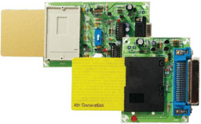
Any application for Smartcard requires what’s commonly referred to as a ‘card reader’. If you’ve read the article on the various types of Smartcards elsewhere in this issue, you already know that a variety of card readers may be required. It all depends on whether you’re dealing with an Open OS card, or a one that’s still blank.
Materials
Gerber file
CAM/CAD data for the PCB referred to in this article is available as a Gerber file. Elektor GREEN and GOLD members can exclusively download these files for free as part of their membership. Gerber files allow a PCB to be produced on an appropriate device available locally, or through an online PCB manufacturing service.
Elektor recommends the Elektor PCB Service service from its business partner Eurocircuits or AISLER as the best services for its own prototypes and volume production.
The use of our Gerber files is provided under a modified Creative Commons license. Creative Commons offers authors, scientists, educators and other creatives the freedom to handle their copyright in a more free way without losing their ownership.
PCB
Component list
Fun/ Jupiter programmer
Resistors
R1,R2,R3 = 220
R4,R5,R9 = 1k
R6,R7,R8 = 10k
R10 = 330
Capacitors
C1 = 10µF 25V radial
C2 = 220nF MKT
C3 = 470µF 25V radial
C4 = 100nF MKT
Semiconductors
IC1 = 78L05
T1 = BC557
T2 = BC547
D1 = 1N4004
LED1 = LED, 5mm, red
Miscellaneous:
K1 = Centronics socket (female), right angle pins
K2 = standard Smartcard connector (e.g., Selectronic no. 60.9292)
K3 = mains adapter socket, PCB mount
JP1 (K4) = SIL pinheader, 3 pins, lead pitch 2.54 mm, with jumper
PCB, ref. 050237-1 from The PCBShop
Phoenix / SmartMouse / JDM reader/programmer
Resistors
R1,R2,R9,R11,R19,R22 = 1k
R3,R12 = 4k7
R4,R6,R7,R8 = 10k
R5 = 10
R10 = 47k
R13 = 22k
R14 = 1k5
R15,R16 = 1M
R17,R18 = 2k2
R20 = 150
R21 = 220
Capacitors:
C1,C3,C5,C7,C8 = 10µF 16V radial
C2,C11 = 10nF ceramic
C4 = 220nF MKT
C6 = 100nF MKT
C9 = 470µF 25V radial
C10 = 1nF MKT
C12 = 47pF ceramic
C13-C16 = 22pF ceramic
Semiconductors
IC1 = 7805
IC2 = MAX232
IC3 = 74HC00
T1 = BC327
T2 = BC557
T3,T4 = BC547
D1,D2,D4,D6,D8,D9 = 1N4148
D3 = 1N4004
D5 = BAT82
D7 = zener diode 13V 0.4 W
LED1 = LED, bicolour, 5 mm, with separate anodes
LED2 = LED, red, 3mm
LED3= LED, yellow, 3mm
Miscellaneous
X1 = 3.579MHz quartz crystal, HC18/U case
X2 = 6MHz quartz crystal, HC18/U case
K1 = 9-way sub-D socket (female), right angle pins, PCB mount
K2 = standard chip card connector (e.g., Selectronic no. 60.9292)
K3 = mains adapter socket, PCB mount PS1 = switch, square, type D6 (ITT)
S1-S4 = 4-way DIP switch block (ASE42FN, Tyco/Alcoswitch) or 4 3-way SIL pinheaders with jumpers
LED1 = 3-way SIL pinheader
S5 = 2-way SIL pinheader with jumper
1 off 14-way DIL IC socket
1 off 16-way DIL IC socket
PCB, ref. 050237-2 from The PCBShop
Resistors
R1,R2,R3 = 220
R4,R5,R9 = 1k
R6,R7,R8 = 10k
R10 = 330
Capacitors
C1 = 10µF 25V radial
C2 = 220nF MKT
C3 = 470µF 25V radial
C4 = 100nF MKT
Semiconductors
IC1 = 78L05
T1 = BC557
T2 = BC547
D1 = 1N4004
LED1 = LED, 5mm, red
Miscellaneous:
K1 = Centronics socket (female), right angle pins
K2 = standard Smartcard connector (e.g., Selectronic no. 60.9292)
K3 = mains adapter socket, PCB mount
JP1 (K4) = SIL pinheader, 3 pins, lead pitch 2.54 mm, with jumper
PCB, ref. 050237-1 from The PCBShop
Phoenix / SmartMouse / JDM reader/programmer
Resistors
R1,R2,R9,R11,R19,R22 = 1k
R3,R12 = 4k7
R4,R6,R7,R8 = 10k
R5 = 10
R10 = 47k
R13 = 22k
R14 = 1k5
R15,R16 = 1M
R17,R18 = 2k2
R20 = 150
R21 = 220
Capacitors:
C1,C3,C5,C7,C8 = 10µF 16V radial
C2,C11 = 10nF ceramic
C4 = 220nF MKT
C6 = 100nF MKT
C9 = 470µF 25V radial
C10 = 1nF MKT
C12 = 47pF ceramic
C13-C16 = 22pF ceramic
Semiconductors
IC1 = 7805
IC2 = MAX232
IC3 = 74HC00
T1 = BC327
T2 = BC557
T3,T4 = BC547
D1,D2,D4,D6,D8,D9 = 1N4148
D3 = 1N4004
D5 = BAT82
D7 = zener diode 13V 0.4 W
LED1 = LED, bicolour, 5 mm, with separate anodes
LED2 = LED, red, 3mm
LED3= LED, yellow, 3mm
Miscellaneous
X1 = 3.579MHz quartz crystal, HC18/U case
X2 = 6MHz quartz crystal, HC18/U case
K1 = 9-way sub-D socket (female), right angle pins, PCB mount
K2 = standard chip card connector (e.g., Selectronic no. 60.9292)
K3 = mains adapter socket, PCB mount PS1 = switch, square, type D6 (ITT)
S1-S4 = 4-way DIP switch block (ASE42FN, Tyco/Alcoswitch) or 4 3-way SIL pinheaders with jumpers
LED1 = 3-way SIL pinheader
S5 = 2-way SIL pinheader with jumper
1 off 14-way DIL IC socket
1 off 16-way DIL IC socket
PCB, ref. 050237-2 from The PCBShop


Discussion (0 comments)