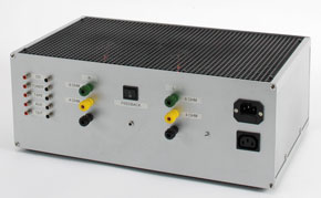
Class-A Triode Push-Pull Amplifier
Tube Sound

It is remarkable that triode output stages still occupy an important place in high-end audio amplifiers. Triode amplifiers are often very expensive. The design presented here is based on a combination of optimal quality and reasonable construction cost.
This is a MEMBER ONLY article. You need a subscription to read this article.
- Unlimited access to online Member Only articles
- 3 new editions Elektor Magazine (digital)
- More than 5000 Gerber files
- 20% member discount on e-books (at elektor.com)
- 10% member discount on Products (at elektor.com)
Available from €5.33 per month.
What is Members Only
Elektor is committed to providing high-quality content on electronics, catering to tens of thousands of paying members. As part of this commitment, Elektor has launched Premium, an initiative that offers exclusive online articles to members sometimes even before they appear in the magazine.
Every day, members can access in-depth articles that showcase the best of Elektor's premium content.
This initiative aims to reward members with early access. Once logged in, members can easily enjoy this exclusive content and engage in discussions about featured projects. While Premium adds to the existing resources available, Elektor will continue to provide a wealth of free information.
Join the Elektor community today to take advantage of Premium and other benefits!
Extra info / Update
In the circuit diagram (Figure 5), capacitors C6 and C7 should have a value of 47 uF, 100 V to match the parts list. C7 is shown with the wrong polarity. Two pins of V2.B are shown incorrectly: pin 8 is the cathode; pin 6 is the anode.
Component list
(all metal film 1%, 0.25W or 0.6W unless otherwise specified)
R1 = 470kΩ
R2 = 390Ω
R3 = 8kΩ2
R4,R5 = 100kΩ 1W
R6 = 33kΩ
R7,R8 = 470kΩ
R9 = 470Ω
R10 = 4kΩ7
R11,R12 = 22kΩ 1W
R13,R14 = 470kΩ
R15,R16 = 1kΩ
R17,R18 = 1kΩ2 6W (wire wound) (1)
R19 = 33kΩ 1W
R20 = 150Ω 5W (wire wound)
R21 = 150kΩ 1W
R22,R23,R24 = 100Ω
P1 = 50kΩ logarithmic law potentiometer
Capacitors
C1 = 150pF ceramic
C2-C5 = 33nF 400V
C6,C7 = 47μF 100V electrolytic
C8 = 10μF 350V electrolytic
C9,C10,C11 = 100μF 350V electrolytic
C12,C13 = 470μF 63V electrolytic
Valves
V1 = 12AX7 or ECC83
V2 = 12AU7 or ECC82
V3 = 6AS7
Semiconductors:
D1-D4 = 1N4007 or bridge rectifier 400V piv @ 1A
D5 = 1N4007
Miscellaneous
Tr1 = mains transformer type 5N1609, primary 230 V, secondary 230V/40V/6.3 V (www.amplimo.nl)
Tr2 = output transformer type 3A524 (www.amplimo.nl)
F1 = fuse, 600mA, slow
F2 = fuse, 300mA, slow
Aluminium corner profile, e.g. # 04.90.2208 (www.tessatronic.nl; www.display.nl)
Self adhesive standoff, e.g., Conrad Electronics # 532037-89
Self adhesive mounting for cable strap, e.g., Conrad Electronics # 543234-89
(1) matching desirable


Discussion (0 comments)