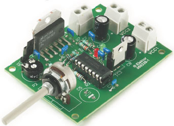
3 Amp PWM DC Motor Controller

This circuit is intended for motion control applications, a common occurrence in robotics! This affordable PWM DC Motor controller can control any PMDC motor specified at 12 V to 30 V and 3 Amps max. Motor direction is controlled with a slide switch and motor speed, with an ordinary potentiometer.
The circuit diagram in Figure 1 shows ICs type LMD18200 and SG3525 at the heart of the circuit. The SG3525 is a pulsewidth modulator control circuit and the LMD18200, an H-Bridge to enable the motor to be run in both directions.
This is a MEMBER ONLY article. You need a subscription to read this article.
- Unlimited access to online Member Only articles
- 3 new editions Elektor Magazine (digital)
- More than 5000 Gerber files
- 20% member discount on e-books (at elektor.com)
- 10% member discount on Products (at elektor.com)
Available from €5.33 per month.
What is Members Only
Elektor is committed to providing high-quality content on electronics, catering to tens of thousands of paying members. As part of this commitment, Elektor has launched Premium, an initiative that offers exclusive online articles to members sometimes even before they appear in the magazine.
Every day, members can access in-depth articles that showcase the best of Elektor's premium content.
This initiative aims to reward members with early access. Once logged in, members can easily enjoy this exclusive content and engage in discussions about featured projects. While Premium adds to the existing resources available, Elektor will continue to provide a wealth of free information.
Join the Elektor community today to take advantage of Premium and other benefits!
Materials
Component list
Resistors
R1 = 10kΩ
R2,R4 = 18kΩ
R3 = 2kΩ2
R5 = 330Ω
R6 = 2kΩ7
R7 = 1kΩ5
P1 = 10kΩ potentiometer
P2 = 100kΩ preset
Capacitors
C1,C2,C4,C5,C7, C9, C10 = 100nF
C3 = 18nF
C5 = 22μF
C6,C8 = 100μF 63V
Semiconductors
D1,D2 = LED
IC1 = SG3525AN
IC2 = LMD18200
IC3 = L7805ACV
Miscellaneous
K1,
S1 = slide switch
PCB, ref. 060339-1 from www.thepcbshop.com


Discussion (0 comments)