

Four-channel logic analyser
Digital Inspector
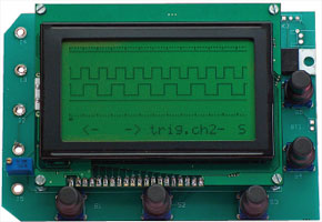
The best way to inspect digital signals is with a logic analyser. Sometimes it's useful to be able to do this on-site, or you may have to take a ‘floating’ measurement. The four-channel logic analyser described here is suitable in both situations due to its compactness and because it can be battery powered. The maximum sampling rate is 2 MHz and the circuit has sufficient memory to store 1024 samples of the signal. The dot-matrix display with a resolution of 64 by 128 pixels shows a clear representation of the digital signals.
This is a MEMBER ONLY article. You need a subscription to read this article.
- Unlimited access to online Member Only articles
- 3 new editions Elektor Magazine (digital)
- More than 5000 Gerber files
- 20% member discount on e-books (at elektor.com)
- 10% member discount on Products (at elektor.com)
Available from €5.33 per month.
What is Members Only
Elektor is committed to providing high-quality content on electronics, catering to tens of thousands of paying members. As part of this commitment, Elektor has launched Premium, an initiative that offers exclusive online articles to members sometimes even before they appear in the magazine.
Every day, members can access in-depth articles that showcase the best of Elektor's premium content.
This initiative aims to reward members with early access. Once logged in, members can easily enjoy this exclusive content and engage in discussions about featured projects. While Premium adds to the existing resources available, Elektor will continue to provide a wealth of free information.
Join the Elektor community today to take advantage of Premium and other benefits!
Materials
Gerber file
CAM/CAD data for the PCB referred to in this article is available as a Gerber file. Elektor GREEN and GOLD members can exclusively download these files for free as part of their membership. Gerber files allow a PCB to be produced on an appropriate device available locally, or through an online PCB manufacturing service.
Elektor recommends the Elektor PCB Service service from its business partner Eurocircuits or AISLER as the best services for its own prototypes and volume production.
The use of our Gerber files is provided under a modified Creative Commons license. Creative Commons offers authors, scientists, educators and other creatives the freedom to handle their copyright in a more free way without losing their ownership.
Extra info / Update
The circuit diagram erroneously shows X1 as a 20 MHz crystal. This should be 10 MHz as stated in the parts list.
Component list
Resistors
R1 = 680Ω
R2,R11-R16 = 10 k
R3-R6 = 330Ω
R7-R10 = 100k
R17 = 56Ω
R19 = 1k
R20 = 47Ω
R21 = 220Ω
P1 = 20kΩ preset, multiturn, vertical mounting
Capacitors
C1,C2 = 22pF
C3-C6 = 100nF
Semiconductors
D1-D10 = 1N4148
D11 = 1N4001
D12 = LED, 5mm diam.
T1,T2 = BC337
IC1 = 74HC04
IC2 = PIC18F4580-I/P, programmed, Elektor SHOP # 060092-41
IC3 = 7805
Miscellaneous
Bz1 = AC buzzer
X1 = 10MHz quartz crystal
Graphic LC display, 128 x 64 pixels, e.g. DEM128064A or NLC128x64 (Conrad Electronics # 187429)
Case 186 x 123 x 41mm with compartment for 9V battery, e.g. Strapubox (Conrad Electronics # 522775)
S1-S5 = pushbutton Multimec RA3FTL6 w. knob AQC09-24.2
S6 = on/off switch
9-V battery clip
5 wander sockets, screw mount (for connection to I1-I5)
Kit of parts incl. case: Elektor SHOP # 060092-71
PCB layout: free download from www.elektor.com, file # 060092-1
Discussion (0 comments)