

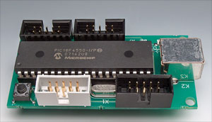
USB Data Acquisition Card
digital & analogue; input & output
This is a MEMBER ONLY article. You need a subscription to read this article.
- Unlimited access to online Member Only articles
- 3 new editions Elektor Magazine (digital)
- More than 5000 Gerber files
- 20% member discount on e-books (at elektor.com)
- 10% member discount on Products (at elektor.com)
Available from €5.33 per month.
What is Members Only
Elektor is committed to providing high-quality content on electronics, catering to tens of thousands of paying members. As part of this commitment, Elektor has launched Premium, an initiative that offers exclusive online articles to members sometimes even before they appear in the magazine.
Every day, members can access in-depth articles that showcase the best of Elektor's premium content.
This initiative aims to reward members with early access. Once logged in, members can easily enjoy this exclusive content and engage in discussions about featured projects. While Premium adds to the existing resources available, Elektor will continue to provide a wealth of free information.
Join the Elektor community today to take advantage of Premium and other benefits!
Materials
Gerber file
CAM/CAD data for the PCB referred to in this article is available as a Gerber file. Elektor GREEN and GOLD members can exclusively download these files for free as part of their membership. Gerber files allow a PCB to be produced on an appropriate device available locally, or through an online PCB manufacturing service.
Elektor recommends the Elektor PCB Service service from its business partner Eurocircuits or AISLER as the best services for its own prototypes and volume production.
The use of our Gerber files is provided under a modified Creative Commons license. Creative Commons offers authors, scientists, educators and other creatives the freedom to handle their copyright in a more free way without losing their ownership.
Extra info / Update
Hardware
In the circuit diagram, the USB+ and USB– pins on K2 should be swapped. The PCB track layout shown in the article should also be corrected. PCBs supplied through the Elektor Shop have the correct USB signal routing and are not affected.
Although different values are indicated in the circuit diagram and the parts list, both 27 Ω and 33 Ω resistors may be used in positions R3 and R4.
Software
Contrary to what some readers have written there is no bug in the firmware CUSTOM_TAD. If it is compiled with MPLAB C18 C Compiler v3.02 as described in the magazine, in the section ‘PIC Firmware’, it compiles perfectly (6 warnings appear, without importance) and the .hex file is generated without problems.
However, if the firmware is compiled with a later version of the C18 Compiler, for instance, with MPLAB C18 C Compiler v3.14 (recent version), some errors appear that inhibit compilation. To be able to compile successfully, the following modifications must be made:
1. File main.c, line 52
Text: #pragma config FCMEM = OFF
Should be: #pragma config FCMEN = OFF
2. File user.c, line 76
Text: OpenPWM2(0xFF);
Should be: TRISCbits.TRISC1=0; CCP2CON=0b00001111;
3. File user.c, line 79
Text: OpenADC(ADC_FOSC_64 & ADC_RIGHT_JUST & ADC_6_TAD,ADC_CH0 & ADC_INT_OFF & ADC_VREFPLUS_VDD & ADC_VREFMINUS_VSS,7);
Should be: OpenADC(ADC_FOSC_64 & ADC_RIGHT_JUST & ADC_6_TAD,ADC_CH0 & ADC_INT_OFF & ADC_REF_VDD_VSS,7);
These tree changes are indispensable. After making the changes the firmware is compiled perfectly (6 warnings appear, without importance) and the .hex file is generated correctly.
To be able to execute the software for the PC it is necessary that Microsoft .NET Framework is installed (free downloaded from Microsoft via Windows Update).
Component list
Resistors
R1 = 10k
R2 = 470
R3,R4 = 33
R5 = 1M
R6,R7,R8 = 1k
Capacitors
(all SMD 0805 case)
C1,C3 = 100nF
C2 = 470nF
C4 = 10nF
C5,C6 = 22pF
Semiconductors
IC1 = PIC18F4550 I/P, programmed, Elektor Shop # 070148-41
D1,D2,D3 = LED, SMD case 1206
Miscellaneous
K1,K3,K4,K5 = 10-way boxheader
X1 = 20MHz quartz crystal
L1 = VK200 or small ferrite bead with 2-4 turns thin enamelled copper wire
S1 = pushbutton, PCB mount, 6mm footprint
DIL40 socket for IC1
PCB (bare), Elektor Shop # 070148-1
Project software, file # 070148-11, free download
Discussion (0 comments)